Hyundai Elantra (CN7): Clutch System / Clutch Cover And Disc
Repair procedures
| Removal |
| 1. | Remove the manual transaxle assembly. (Refer to Manual Transaxle System - "Manual Transaxle") |
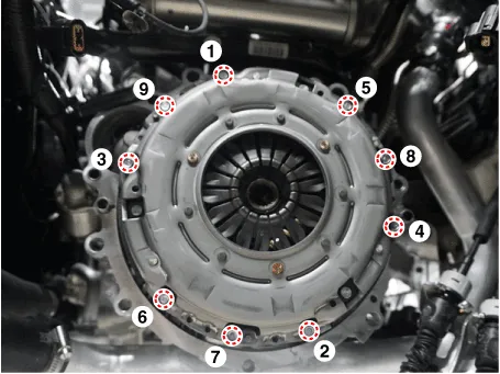
| 2. | Remove the clutch cover assembly after loosening the bolts.
[Gasoline 1.6 MPI / Gasoline 1.6 T-GDI]
[Gasoline 2.0 MPI]
|


| Inspection |
| 1. | Inspect diaphragm spring wear which is in contact with a concentric slave cylinder bearing. |
| 2. | Check the clutch cover and disc surface for wear or cracks. |
| 3. | Check the clutch disc facing for slipping or oil marks. |
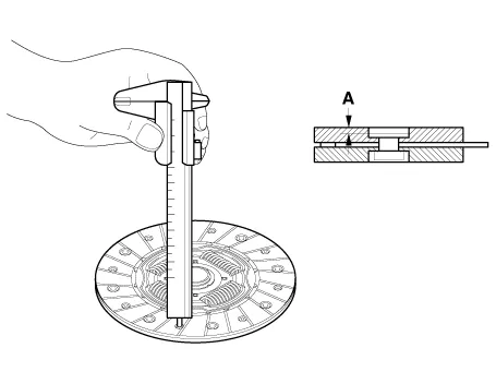
| 4. | Measure the depth from a clutch facing surface to a rivet. If the measured value is less than the specification below, replace it.
|
| Installation |
|
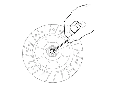
| 1. | Apply grease on a disc spline part and transaxle input shaft spline part as required.
|

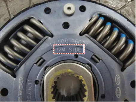
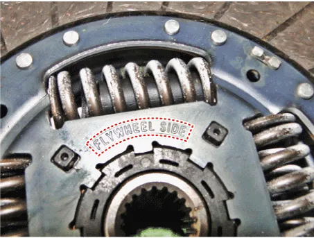
| 2. | Before installing the clutch disc, check the “TM SIDE” and “FLYWHEEL SIDE” marked on the clutch disc, and install it with the clutch cover using a special tool (09411-1P000).
|
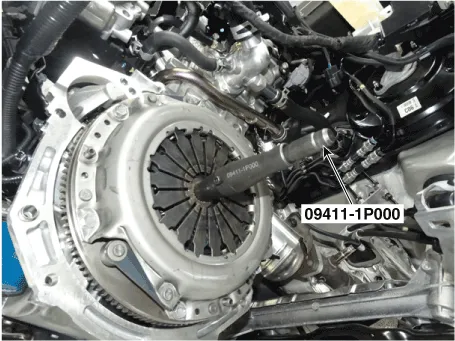
| 3. | Install the clutch disc and the cover with SST (A: 09411-1P000).
|
| 4. | Install the clutch cover mounting bolts.
|
| 5. | Remove the clutch disc guide SST (No.: 09411-1P000).
|
| 6. | Install the transaxle assembly. (Refer to Manual Transaxle System - "Manual Transaxle") |
Description and operation Description– Clutch operation is detected through clutch switch signal. This signal enables ECM to cope with instant change of load condition.
Other information:
Hyundai Elantra (CN7) 2021-2026 Service Manual: Evaporator Temperature Sensor
Description and operation DescriptionThe evaporator temperature sensor will detect the evaporator core temperature and interrupt compressor relay power in order to prevent evaporator from freezing by excessive cooling. The evaporator temperature sensor has the Negative Temperature Coefficient (NTC).
Hyundai Elantra (CN7) 2021-2026 Service Manual: Heater Core
Repair procedures Replacement1.Disconnect the negative (-) battery terminal. 2.Remove the heater and blower assembly.(Refer to Heater - "Heater Unit") 3.Remove the heater core cover (A) after loosening the mounting screws.4.Pull out the heater core (A) from the heater unit.
Categories
- Manuals Home
- Hyundai Elantra Owners Manual
- Hyundai Elantra Service Manual
- Specifications
- Maintenance
- Driver assistance system
- New on site
- Most important about car
