Hyundai Elantra (CN7): IMS(Integrated Memory System) / Components and components location
| Components |
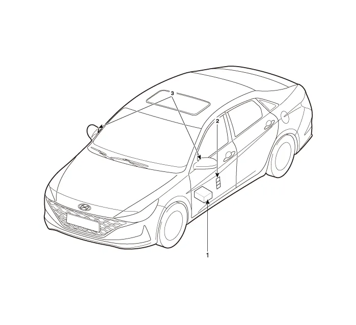
| 1. Memory power seat unit (PSM) 2. IMS control switch | 3. Outside Mirror |
DescriptionThe changed position of the seat by memorizing into the power seat unit with IMS switch controlling the optimal seat position set by the driver can be restored with the IMS switch.
Specifications[Memory Power Seat Unit ] Item Specifications Rated voltageDC 12VOperating VoltageDC 9V - 16VOperating Temperature Range-30°C to 75°C Dark currentMax.
Other information:
Hyundai Elantra (CN7) 2021-2026 Service Manual: Specifications
SpecificationAir Conditioner Item Specification CompressorTypeGamma 1.6 MPI, Gasoline 2.0 NU MPI, Gasoline 1.6 T-GDI : 6HVx14Gasoline 1.6 MPI : 6HVe14Oil type & CapacityFD46XG (IDEMITSU) 100 ± 10 g Pulley type6PK-TYPEDisplacement145 cc/revExpansion valveTypeBlock type RefrigerantTypeR - 134
Hyundai Elantra (CN7) 2021-2026 Service Manual: Mode Control Actuator
Description and operation DescriptionThe mode control actuator is located at the heater unit.It adjusts the position of the mode door by operating the mode control actuator based on the signal of the A/C control unit. Pressing the mode select switch makes the mode control actuator shift in order of Vent → Bi-Level → Floor → Mix.
Categories
- Manuals Home
- Hyundai Elantra Owners Manual
- Hyundai Elantra Service Manual
- Drive Mode
- Rear Seats
- Front Radar Unit
- New on site
- Most important about car
