Hyundai Elantra (CN7): Driveshaft and axle / Front Axle Assembly. Front Hub / Knuckle / Tone Wheel
Hyundai Elantra (CN7) 2021-2026 Service Manual / Driveshaft and axle / Front Axle Assembly. Front Hub / Knuckle / Tone Wheel
Components and components location
| Components |
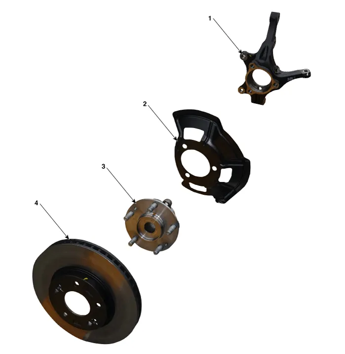
| 1. Front knuckle 2. Dust cover | 3. Hub bearing 4. Brake disc |
Repair procedures
| Removal |
| 1. | Loosen the wheel nuts slightly. Raise the vehicle, and make sure it is securely supported. |
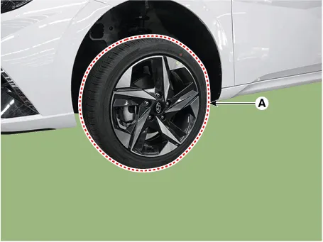
| 2. | Remove the front wheel and tire (A) from the front hub.
|

| 3. | Remove the front brake caliper. (Refer to Brake System - "Front Disc Brake") |
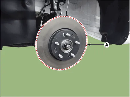
| 4. | Loosen the screw and the remove the front disc (A).
|
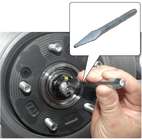
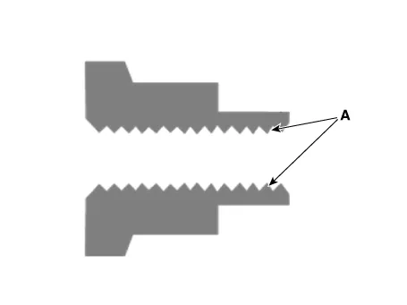
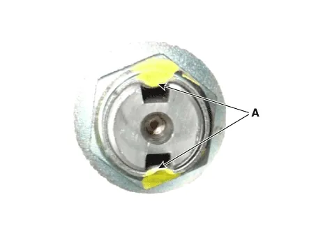
| 5. | By hammering on a chisel, unlock the driveshaft lock hub nut caulking.
|
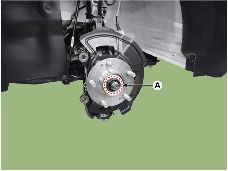
| 6. | Loosen the driveshaft caulking nut (A) from the front hub.
|

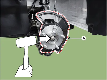
| 7. | Loosen the mounting bolts from the knuckle and then remove the hub bearing assembly and dust cover (A) by using the plastic hammer.
|
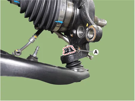
| 8. | Remove the tie rod end ball joint by using the special service tool.
|
| 9. | Remove the wheel speed sensor (A) from the knuckle after loosening the mounting bolt.
|
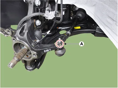
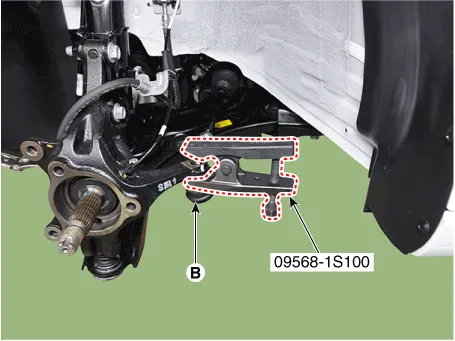
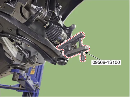
| 10. | Separate the lower arm ball joint by using the SST (09568-1S100) after loosening the lower arm mounting nut (A).
|
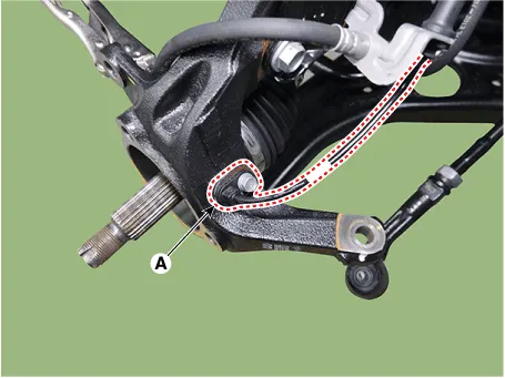
| 11. | Remove the front knuckle (A) after loosening the bolts and nuts.
|

| Inspection |
| 1. | Check the hub for cracks and the splines for wear. |
| 2. | Check the brake disc for scoring and damage. |
| 3. | Check the knuckle for cracks. |
| 4. | Check the bearing for cracks or damage. |
| Installation |
| 1. | To install, reverse the removal procedures. |
| 2. | Check the alignment. (Refer to Suspension System - "Alingment") |
Special Service Tools Tool (Number and Name) Illustration Use 09495-3K000Band installerInstallation of ear type boot band09495-39100Band installerInstallation of hook type boot band09568-1S100Ball joint pullerRemove the ball joint front axle 09495-33000PullerRemove the spider assembly from the drive shaft
Other information:
Hyundai Elantra (CN7) 2021-2026 Service Manual: Special service tools
S
Hyundai Elantra (CN7) 2021-2026 Service Manual: Heater & A/C Control Unit (DATC)
Components and components location Components[This illustration shows the LHD type. RHD type is symmetrical.][Connector A] Pin No Function Pin No Function 1Battery9IGN22ILL+ (TAIL)10ISG Battery (+)3-11IGN14LIN BUS12HTD5-13-6-14-7-15-8RHEO (
Categories
- Manuals Home
- Hyundai Elantra Owners Manual
- Hyundai Elantra Service Manual
- General Tightening Torque Table. General information
- Engine Mechanical System
- Rear Seats
- New on site
- Most important about car

Copyright © 2026 www.helantra7.com - 0.0243