Hyundai Elantra (CN7): Charging System / Alternator
Description and operation
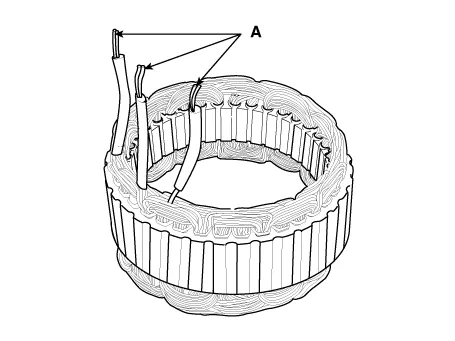
| Description |
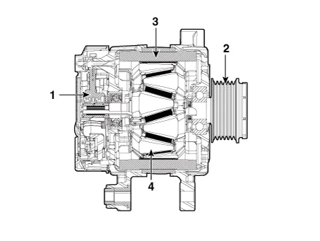
| 1. Brush 2. Drive belt pully 3. Stator 4. Rotor |
Specifications
| Specification |
|
Item
|
Specification
| |
| Rated voltage | 13.5V, 130A | |
| Speed in use | 1,000 - 18,000 rpm | |
| Voltage regulator | IC Regulator built-in type | |
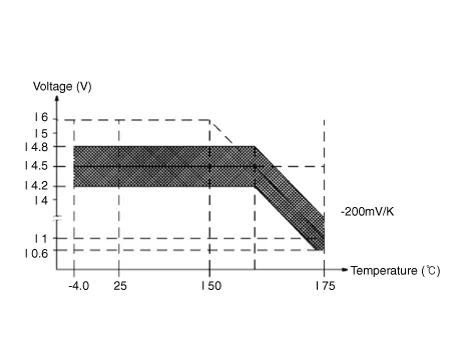
| Regulator Setting Voltage | External mode | 10.6 - 16 ± 0.3V |
| Internal mode | 14.55 ± 0.3V | |
| Temperature Gradient | External mode | 0 ± 2 mV / °C |
| Internal mode | -3.5 ± 2mV / °C | |
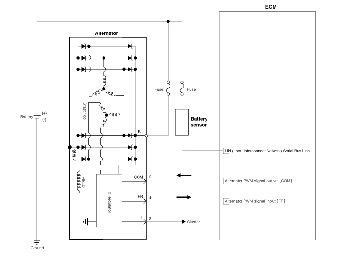
Schematic diagrams
| Circuit Diagram |
|

Repair procedures
| Removal |
| 1. | Turn ignition switch OFF and disconnect the negative (-) battery cable. |
| 2. | Remove the drive belt tensioner. (Refer to Engine Mechanical System - "Drive Belt Tensioner") |
| 3. | Remove the drive belt. (Refer to Engine Mechanical System - "Drive Belt") |
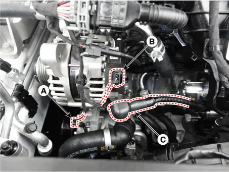
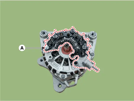
| 4. | Remove return hose & pipe braket bolt (A).
|
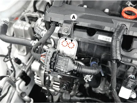
| 5. | Disconnect the cable (C) from alternator "B" terminal after disconnect the compressor connector (A) and the alternator connector (B).
|
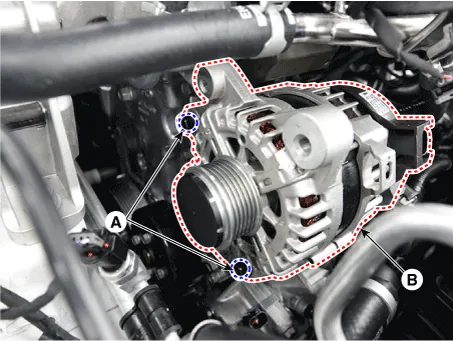
| 6. | Remove the alternator (B) after loosening the mounting nuts (A).
|
| Installation |
| 1. | Install in the reverse order of removal. |
| Disassembly |
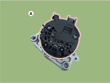
| 1. | Remove the rear cover (A).
|
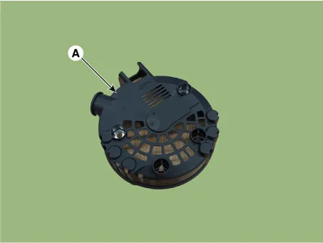
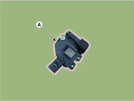
| 2. | Remove the mounting bolts and the regulator assembly (A).
|


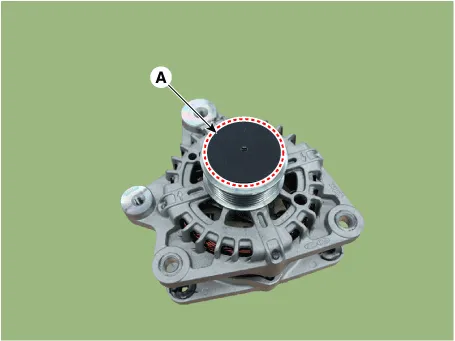
| 3. | Remove the OAP cap (A).
|
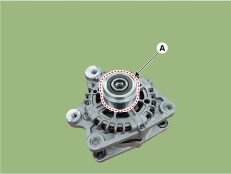
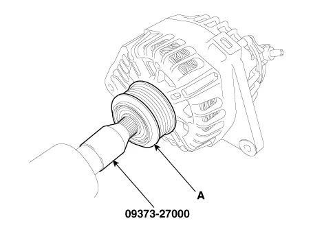
| 4. | Remove the OAP pulley (A) by using the SST (09373-27000).
|
| 5. | Remove the rectifier assembly (A) after disconnecting the stator leads.
|
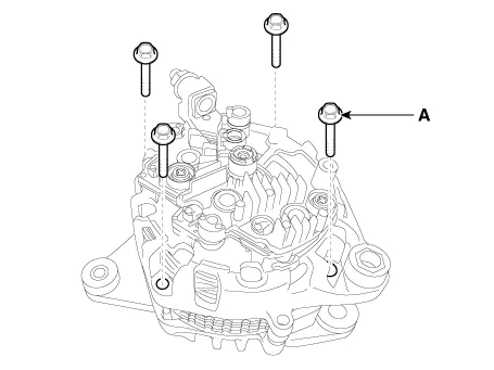
| 6. | Remove the through bolts (A).
|
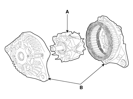
| 7. | Disconnect the rotor (A) and housing (B).
|
| Reassembly |
| 1. | Reassemble in the reverse order of disassembly. |
| Inspection |
| 1. | Check that there is continuity between the slip rings (C).
|
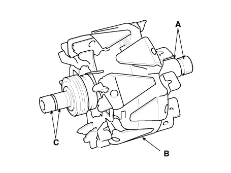
| 2. | Check that there is no continuity between the slip ring (C) and the rotor (B) or rotor shaft (A). |
| 3. | If the rotor fails either continuity check, replace the alternator. |
| 1. | Check that there is continuity between each pair of leads (A).
|
| 2. | Check that there is no continuity between each lead and the coil core. |
| 3. | If the coil fails either continuity check, replace the alternator. |
InspectionInspecion Item• Battery efficiency inspection• Battery voltage inspection• Charging voltage insptection• General inspection• Terminal tightening state inspection• Engine/ transaxle ground state inspection• Wiring hareness ground state inspection• Electrical Specified Value Inspection• Vehicle parasitic current inspection • Inspect the battery capacityBattery Efficiency Inspection • Check that the battery cables are connected to the correct terminals.
Description and operation Description1.The CMF (Closed Maintenance Free) battery is, as the name implies, totally maintenance free and has no removable battery cell caps.
Other information:
Hyundai Elantra (CN7) 2021-2026 Service Manual: Head Lamp Leveling Device
Components and components location Component Location1. Head lamp leveling actuator2. Head lamp leveling switch Head Lamp Leveling Switch Schematic diagrams Schematic Diagrams Repair procedures Replacement1.Disconnect the negative (-) battery terminal.
Hyundai Elantra (CN7) 2021-2026 Service Manual: Description and operation
DescriptionRear Corner Radar is a system that measures the relative speed and distance from the following vehicles by using two electromagnetic wave radar sensors attached to the rear bumper, and detects any vehicle within the blind spot zone and gives off alarm.
Categories
- Manuals Home
- Hyundai Elantra Owners Manual
- Hyundai Elantra Service Manual
- Rear Seats
- Engine Control / Fuel System
- Components and components location
- New on site
- Most important about car
