
Hyundai Elantra (CN7): Front Radar System / Components and components location
| Components Location |
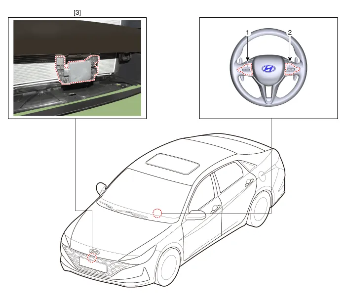
| 1. Remote control switch (LH : Audio swtich) 2. Remote control switch (RH : Cruse) | 3. Front rader unit |
Description and operation The System may be limited when • The radar sensor or camera is blocked with a foreign object or debris.
Components and components location Components Location1. Front rader unit Specifications Specification Item Specification Power supply (V)12Operation voltage (V)9 - 16 Schematic diagrams Circuit DiagramTerminal function Pin No Terminal function 1GROUND2L-CAN HIGH3L-CAN LOW4C-CAN HIGH5C-CAN LOW6IGN Repair procedures InspectionInspection procedure for vehicle with Forward Collision-Avoidance Assist and Smart Cruise Control system failure 1.
Other information:
Hyundai Elantra (CN7) 2021-2026 Service Manual: Evaporator Core
Repair procedures Replacement1.Disconnect the negative (-) battery terminal. 2.Remove the heater and blower assembly.(Refer to Heater - "Heater Unit") 3.Remove the heater core cover (A) after loosening the mounting screws.4.Pull out the evaporator core (A) from the heater unit.
Hyundai Elantra (CN7) 2021-2026 Service Manual: Troubleshooting
Diagnosis with Diagnostic tool1.In the body electrical system, failure can be quickly diagnosed by using the vehicle diagnostic system (Diagnostic tool).The diagnostic system (Diagnostic tool) provides the following information.(1)Fault Code Searching : Checking failure and code number (DTC)(2)Data Analysis : Checking the system input/output data s
Categories
- Manuals Home
- Hyundai Elantra Owners Manual
- Hyundai Elantra Service Manual
- Maintenance
- Vehicle Information
- Function settings
- New on site
- Most important about car
