Hyundai Elantra (CN7): Heater / Evaporator Core
Hyundai Elantra (CN7) 2021-2026 Service Manual / Heating, Ventilation and Air Conditioning / Heater / Evaporator Core
Repair procedures
| Replacement |
| 1. | Disconnect the negative (-) battery terminal. |
| 2. | Remove the heater and blower assembly. (Refer to Heater - "Heater Unit") |
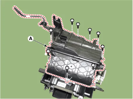
| 3. | Remove the heater core cover (A) after loosening the mounting screws.
|
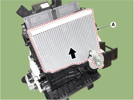
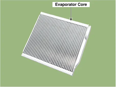
| 4. | Pull out the evaporator core (A) from the heater unit.
|
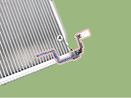
| 5. | Remove the evaporator temperature sensor (A).
|
| 6. | To install, reverse the removal procedure.
|

Repair procedures Replacement1.Disconnect the negative (-) battery terminal. 2.Remove the heater and blower assembly.(Refer to Heater - "Heater Unit") 3.
Description and operation DescriptionThe temperature control actuator is located at the heater unit. It regulates the temperature by the procedure as follows.
Other information:
Hyundai Elantra (CN7) 2021-2026 Service Manual: Components and components location
C
Hyundai Elantra (CN7) 2021-2026 Service Manual: Repair procedures
Inspection1.Check for resistance between terminals in each switch position (LH).[LH : Audio + Hands free] Switch Resistance (±5%) SEEK Up430 ΩSEEK Down1.11 kΩMODE2.11 kΩMUTE3.11 kΩVolume (+)4.
Categories
- Manuals Home
- Hyundai Elantra Owners Manual
- Hyundai Elantra Service Manual
- Troubleshooting
- Auto Hold. Warning messages
- Engine Control / Fuel System
- New on site
- Most important about car

Copyright © 2026 www.helantra7.com - 0.0116