Hyundai Elantra (CN7): Cruise Control System (CC) / Repair procedures
| Inspection |
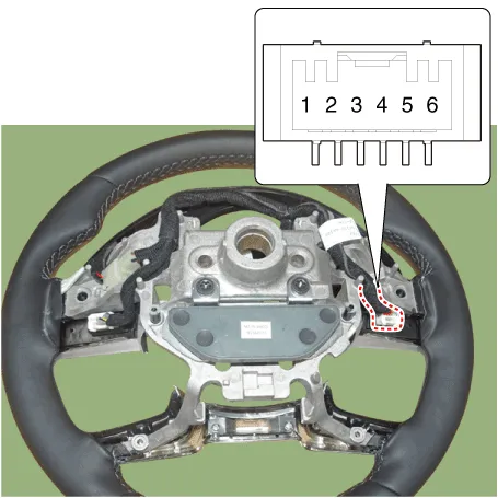
| 1. | Check for resistance between terminals in each switch position (LH).
[LH : Audio + Hands free]
|
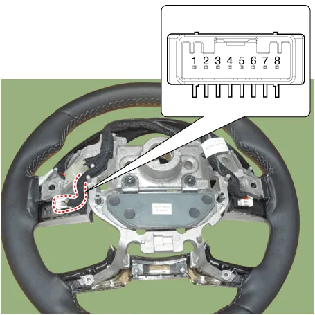
| 2. | Check for resistance between terminals in each switch position (RH).
[Cruise]
[Trip]
|
| Removal |
| 1. | Disconnect the negative (-) battery terminal. |
| 2. | Remove the steering wheel assembly. (Refer to Steering System - "Steering Wheel") |
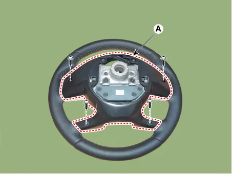
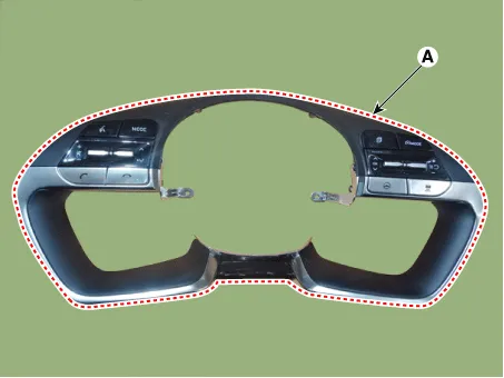
| 3. | Remove the steering back cover (A).
|
| 4. | Remove the steering remote control connector (A).
|

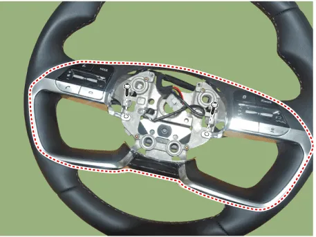
| 5. | Remove the steering remote control(Switch (A)) after loosening the screws.
|
| Installation |
| 1. | Install the steering wheel remote control after connecting the connector. |
| 2. | Install the steering wheel. |
| 3. | Connect the negative (-) battery terminal. |
Schematic Diagrams
Other information:
Hyundai Elantra (CN7) 2021-2026 Service Manual: Description and operation
DescriptionThe immobilizer system will disable the vehicle unless the proper ignition key is used, in addition to the currently available anti-theft systems such as car alarms, the immobilizer system aims to drastically reduce the rate of auto theft.1.
Hyundai Elantra (CN7) 2021-2026 Service Manual: Antenna Coil
Repair procedures Removal1.Disconnect the negative (-) battery terminal.2.Remove the crash pad lower panel.(Refer to Body - "Crash Pad Lower Panel")3.Remove the steering column shroud panel.(Refer to Body - "Steering Column Shroud Panel")4.Disconnect the immobilizer connector (A) and press the locking pin (B) using an awl.
Categories
- Manuals Home
- Hyundai Elantra Owners Manual
- Hyundai Elantra Service Manual
- Integrated Thermal Management Module (ITM)
- Front Bumper
- Brake System
- New on site
- Most important about car

Copyright © 2026 www.helantra7.com - 0.0224