Hyundai Elantra (CN7): Engine Control System / Integrated Thermal Management Module (ITM)
Description and operation
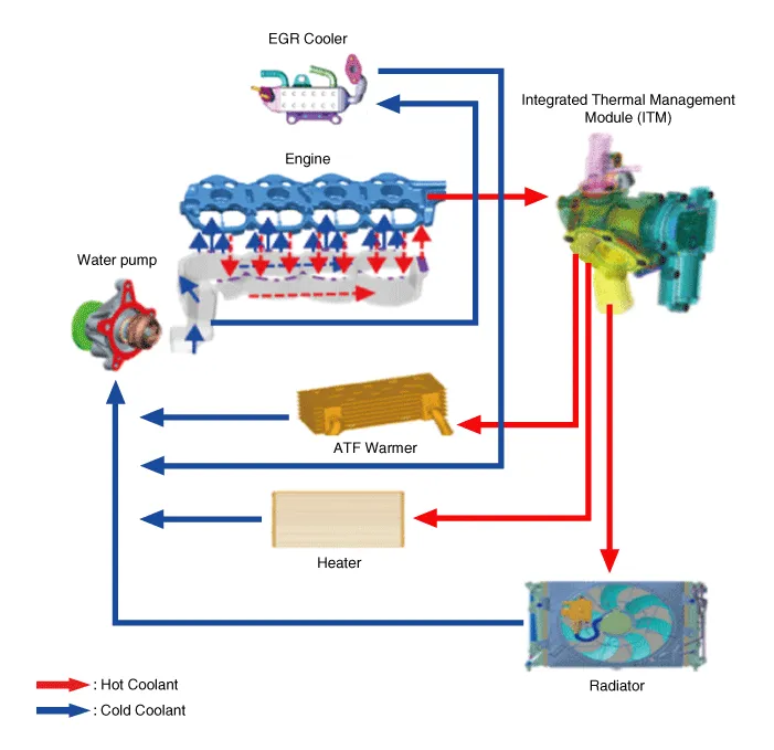
| Description |
Components and components location
| Components |
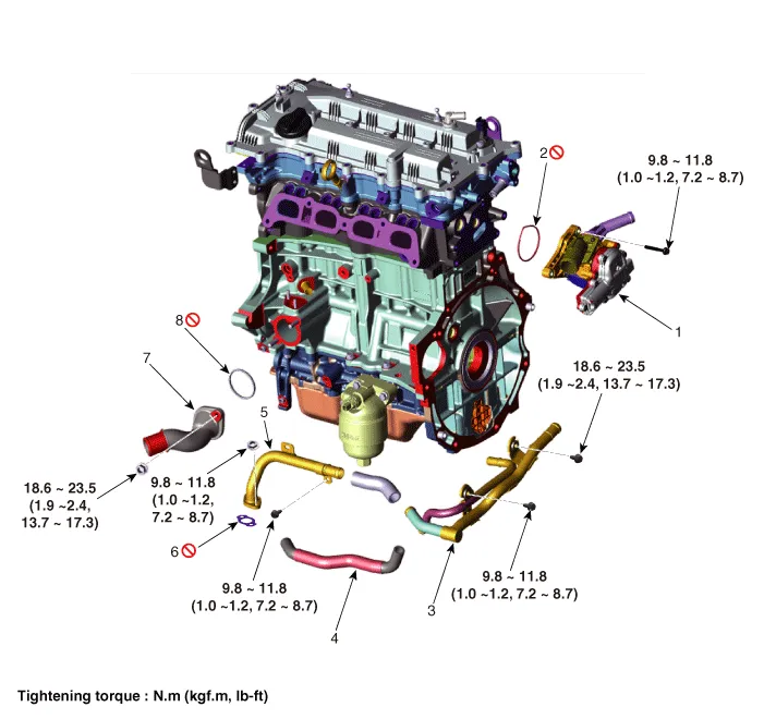
| 1. Integrated thermal management module (ITM) 2. Integrated thermal management module (ITM) O-ring 3. Heater pipe B 4. Heater water hose | 5. Heater pipe A 6. Heater pipe A gasket 7. Water inlet fitting 8. Water inlet fitting gasket |
Schematic diagrams
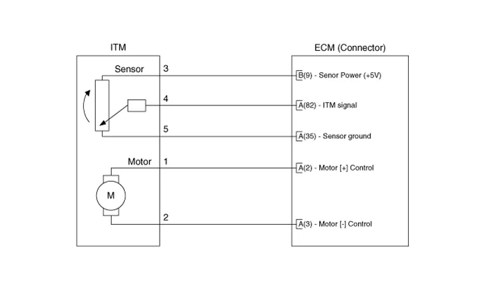
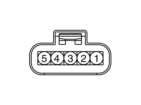
| Circuit Diagram |
Repair procedures
| Removal and Installation |
| 1. | Remove the integrated thermal management module (ITM). (Refer to Engine Mechanical System - "Integrated Thermal Management Module (ITM)")
|

| 2. | Install in the reverse order of removal. |
| Inspection |
| 1. | Turn the ignition switch OFF. |
| 2. | Connect the diagnostic tool to data link connector (DLC). |
| 3. | Turn the ignition switch ON. |
| 4. | Select the "Veichle, Model Year, Engine Specification, System". |
| 5. | Connect a diagnostic tool and then operate the integrated thermal management motor (ITM). |
| 6. | Confirm the Integrated thermal management motor (ITM) proper operation. |
| 7. | When the DTC occur, refer to the DTC guide. |
Description and operation DescriptionRCV (Recirculation Valve) Control Solenoid Valve is installed on the intercooler inlet pipe and operates the RCV actuator which controls the by-pass passage of the turbocharger compressor.
Description and operation DescriptionCVVD(Continuous Variable Valve Duration) System is a device to control the optimum open and close timing according to the driving mode by changing the valve opening section.
Other information:
Hyundai Elantra (CN7) 2021-2026 Service Manual: Wireless Power Charging Unit
Components and positions Components Circuit diagram Circuit Diagram Repair procedures Removal • Handling wireless charging system parts by wet hands may cause electric shock. 1.Disconnect the negative (-) battery terminal.
Hyundai Elantra (CN7) 2021-2026 Service Manual: Blower Unit
Components and components location Component Location1. Blower unit assemblyComponents1. Blower unit assebmly2. Blower upper cover [LH]3. Duct seal4. Blower upper cover [RH]5. Intake actuator6. Air filter cover7. Intake door8. Air filter9. Blower upper case10.
Categories
- Manuals Home
- Hyundai Elantra Owners Manual
- Hyundai Elantra Service Manual
- Instrument Panel Overview
- Front Bumper
- Front Radar Unit
- New on site
- Most important about car
