Hyundai Elantra (CN7): Wireless Power Charger System / Wireless Power Charging Unit
Components and positions
| Components |
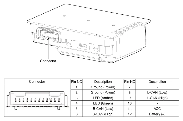
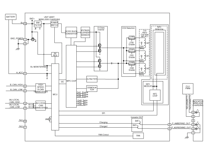
Circuit diagram
| Circuit Diagram |
Repair procedures
| Removal |
|

| 1. | Disconnect the negative (-) battery terminal. |
| 2. | Remove the floor console upper cover assembly. (Refer to Body - "Floor Console Upper Cover") |
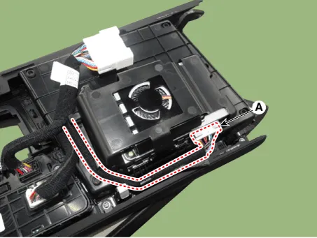
| 3. | Disconnect the connector (A) and remove the wireless power charger unit.
|
| Installation |
| 1. | Install the wireless power charging unit. |
| 2. | Connect the wireless power charging unit connectors. |
| 3. | Install the floor console upper cover. |
| 4. | Connect the negative (-) battery terminal. |
| [Diagnosis With Diagnostic tool] |
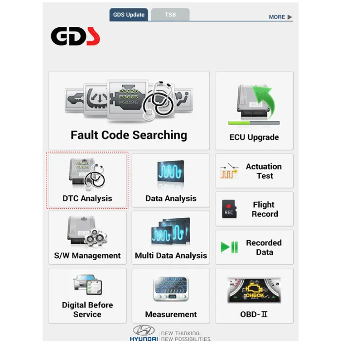
| 1. | In the body electrical system, failure can be quickly diagnosed by using the vehicle diagnostic system (Diagnostic tool). The diagnostic system(Diagnostic tool) provides the following information.
|
| 2. | If diagnose the vehicle by Diagnostic tool, select "DTC Analysis" and "Vehicle".
|
| 3. | If check current status, select the "Data Analysis" .
|
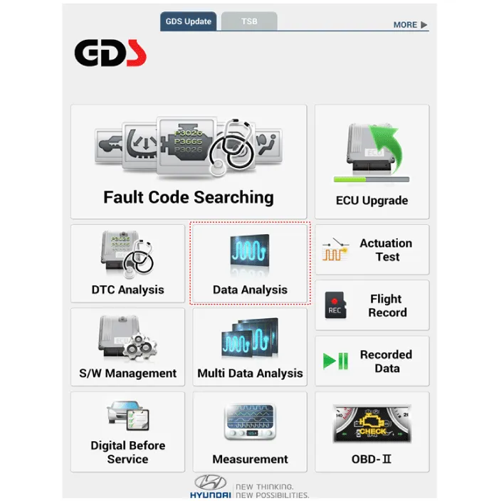
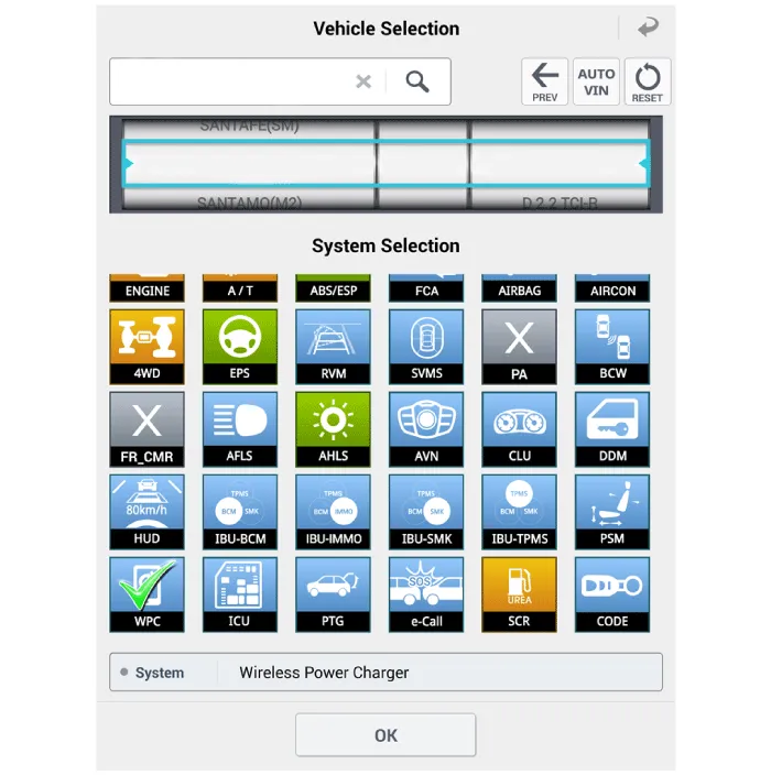
| 4. | Select the 'WPC' to search the current state of the input/output data.
|
Specifications Item Specification Rated voltageDC 12VOperating voltageDC 9.0 - 16.0VOperating temperature-86 to 167°F (-30 to 75°C)Dark currentMAX 1mAOutput power5 WOutput frequency110 ± 5 kHz
Components and positions Components Repair procedures Removal • Handling wireless charging system parts by wet hands may cause electric shock.
Other information:
Hyundai Elantra (CN7) 2021-2026 Service Manual: Auto Defogging Sensor
Description DescriptionThe auto defogging sensor is installed on the front window glass. The sensor judges and sends signal if moisture occurs to blow out wind for defogging. The air conditioner control module receives signal from the sensor and restrains moisture and eliminate defog by controlling the intake actuator, A/C, auto defogging actuat
Hyundai Elantra (CN7) 2021-2026 Service Manual: Heater & A/C Control Unit (DATC)
Components and components location Components[This illustration shows the LHD type. RHD type is symmetrical.][Connector A] Pin No Function Pin No Function 1Battery9IGN22ILL+ (TAIL)10ISG Battery (+)3-11IGN14LIN BUS12HTD5-13-6-14-7-15-8RHEO (
Categories
- Manuals Home
- Hyundai Elantra Owners Manual
- Hyundai Elantra Service Manual
- Suspension System
- Instrument Panel Overview
- Repair procedures
- New on site
- Most important about car
