Hyundai Elantra (CN7): Wireless Power Charger System / Components and positions
| Components |
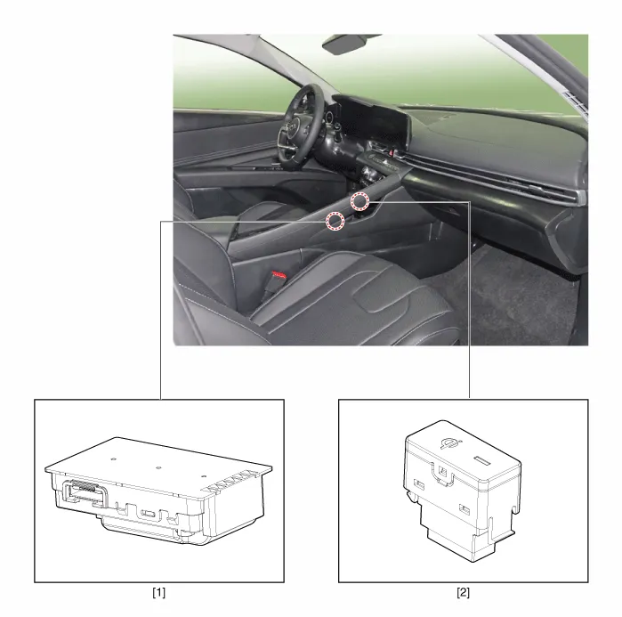
| 1. Wireless power charging unit | 2. Wireless power charging lamp |
Description and OperationWireless Power Charger SystemDuring ACC or IG ON, battery voltage is supplied to the wireless power charger system to transmit an output of 5 W to mobile phone.
TroubleshootingWireless Power Charger System Troubleshooting Trouble status Inspection item Inspection Not chargedCheck the mobile phone status R-1Amber LED blinks OvercurrentR-2OverheatingR-2Foreign matterR-2R-1.
Other information:
Hyundai Elantra (CN7) 2021-2026 Service Manual: Compressor oil
Repair procedures Oil Specification1.The HFC-134a system requires synthetic (PAG) compressor oil whereas the R-12 system requires mineral compressor oil. The two oils must never be mixed.2.Compressor (PAG) oil varies according to compressor model. Be sure to use oil specified for the model of compressor.
Hyundai Elantra (CN7) 2021-2026 Service Manual: Components and components location
C
Categories
- Manuals Home
- Hyundai Elantra Owners Manual
- Hyundai Elantra Service Manual
- Repair procedures
- Auto Hold. Warning messages
- Specifications
- New on site
- Most important about car
