Hyundai Elantra (CN7): Wireless Power Charger System / Wireless Charging Lamp
Components and positions
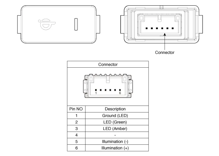
| Components |
Repair procedures
| Removal |
|

| 1. | Disconnect the negative (-) battery terminal. |
| 2. | Remove the floor console upper cover assembly. (Refer to Body - "Floor Console Upper Cover") |
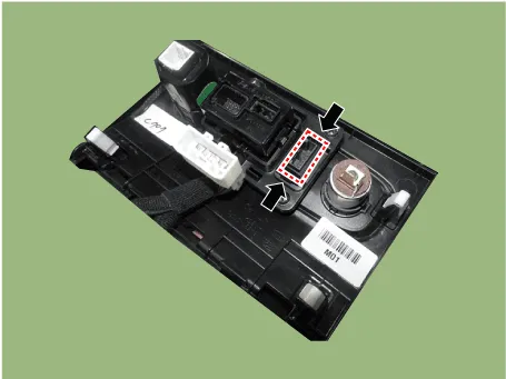
| 3. | Push the lock pin and remove the wireless charging lamp.
|
| Installation |
| 1. | Install the wireless charging lamp. |
| 2. | Install the floor console upper cover assembly. |
| 3. | Connect the negative (-) battery terminal. |
Components and positions Components Circuit diagram Circuit Diagram Repair procedures Removal • Handling wireless charging system parts by wet hands may cause electric shock.
Other information:
Hyundai Elantra (CN7) 2021-2026 Service Manual: Mood Lamp
Repair procedures RemovalMood lamp unit1.Disconnect the negative (-) battery terminal.2.Remove the main crash pad assembly.(Refer to Body - "Main Crash Pad Assembly")3.Loosen the mounting screws and remove the main crash pad air duct (A).4.Loosen the mounting screws and remove the mood lamp unit (A).
Hyundai Elantra (CN7) 2021-2026 Service Manual: Auto Lighting Control System
Description and operation DescriptionIt's a system that uses illumination sensor to automatically turn ON the tail lamp and head lamp based on the change in surrounding environment's illumination condition. It activates when the vehicle enters/exits tunnel, or when the illumination condition in surrounding environment changes due to rain, snow, or
Categories
- Manuals Home
- Hyundai Elantra Owners Manual
- Hyundai Elantra Service Manual
- Driver assistance system
- Front Bumper
- Engine Control / Fuel System
- New on site
- Most important about car
