Hyundai Elantra (CN7): Body Electrical System / Auto Lighting Control System
Hyundai Elantra (CN7) 2021-2026 Service Manual / Body Electrical System / Auto Lighting Control System
Description and operation
| Description |
It's a system that uses illumination sensor to automatically turn ON the tail lamp and head lamp based on the change in surrounding environment's illumination condition. It activates when the vehicle enters/exits tunnel, or when the illumination condition in surrounding environment changes due to rain, snow, or fog. Precautions corresponding to the use of this system are as follows.
| 1. | Do not add another device on top of this device. |
| 2. | Be sure to switch to manual during poor visibility climate, such as fog, heavy rain, or cloudy weather. |
| 3. | Illumination intensity in an actual vehicle is not always constant, and lamp ON/OFF time may very depending on the climate, season, and surrounding environment. |
| 4. | Use this system only during sunrise and sunset period, and manually control lamp ON/OFF for general conditions. |
| 5. | Error may occur if light block coating that may change interior illumination is applied. |
Components and components location
| Component Location |
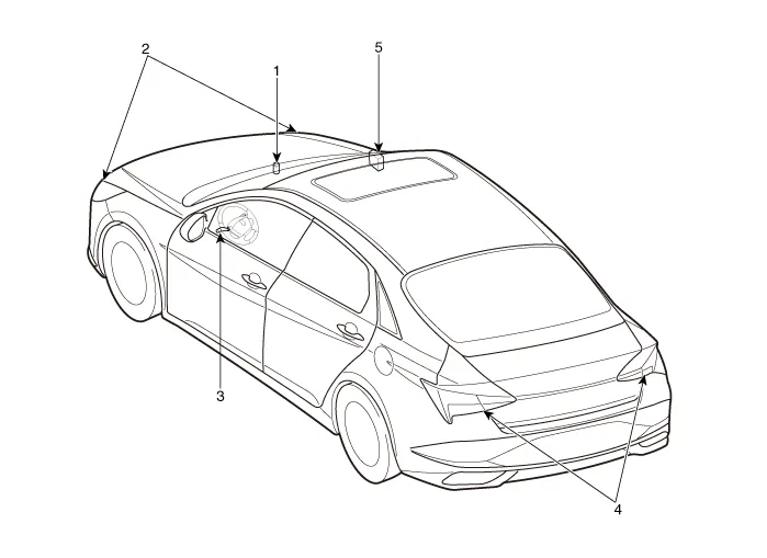
| 1. Auto light sensor 2. Head lamps 3. Lighting switch (Auto) | 4. Rear combination lamps 5. Integrated body control unit (IBU) |
Specifications
| Specifications |
|
Items
|
Specifications
| |
| Rated voltage | 5V | |
| Load | Max. 1mA (Relay load) | |
| Illuminations (LUX) | 100 | 0.76 ± 0.17V |
| 150 | 1.3 ± 0.30V | |
Schematic diagrams
| Circuit Diagram |
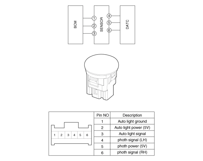
Auto Light Sensor
Repair procedures
| Inspection |
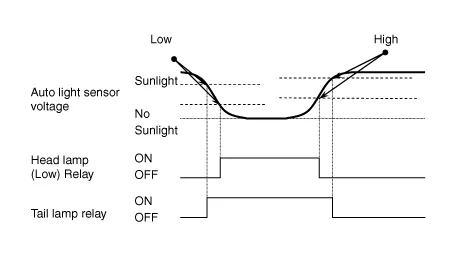
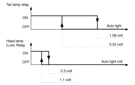
Check if the auto light control operates like a timing chart shown below. Tail lamp output and head lamp (Low) output is controlled based on the auto light sensor's input (illumination intensity) when the Auto Light Switch in Multi-Function Switch is turned ON, and the vehicle is in IGN1 or IGN2 ON Mode. If IGN1 = ON, BCM detects this voltage, and if the voltage exceeds rated voltage, then auto light failure occurs. (below 4V or above 6V)
|

In the state of IGN1 ON, when multi function switch module detects auto light switch on, tail lamp relay output and head lamp low relay output are controlled according to auto light sensor's input.The auto light control doesn't work if the pin sunlight supply (5V regulated power from Ignition 1 power to sunlight sensor) is in short circuit with the ground.If IGN1 ON, The BCM monitors the range of this supply and raises up a failure as soon as the supply’s voltage is out of range. Then this failure occurs and as long as this is present, the head lamp must be turned on without taking care about the sunlight level provided by the sensor.This is designed to prevent any head lamp cut off when the failure occurs during the night.
| Removal |
|
| 1. | Disconnect the negative ( - ) battery terminal. |
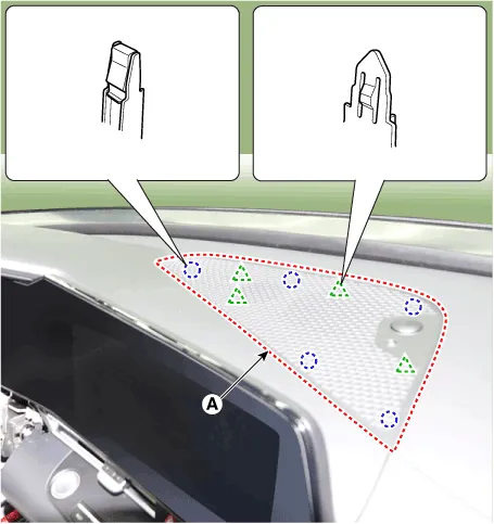
| 2. | Using a remover and remove the crash pad center speaker grille (A).
|
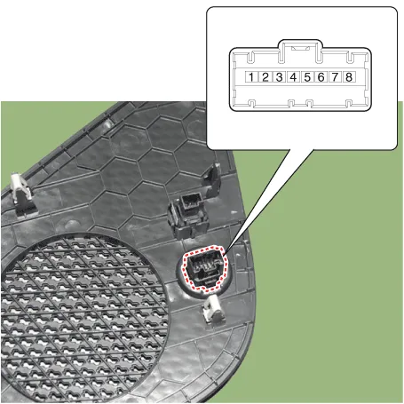
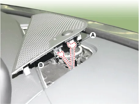
| 3. | Disconnect the auto light sensor connector (A) and security sensor connector (B).
|
| Installation |
| 1. | Connect the auto light sensor connector and security sensor connector. |
| 2. | Install the crash pad center speaker grille. |
Repair procedures RemovalMood lamp unit1.Disconnect the negative (-) battery terminal.2.Remove the main crash pad assembly.(Refer to Body - "Main Crash Pad Assembly")3.
Components and components location Component Location1. Head lamp leveling actuator2. Head lamp leveling switch Head Lamp Leveling Switch Schematic diagrams Schematic Diagrams Repair procedures Replacement1.
Other information:
Hyundai Elantra (CN7) 2021-2026 Service Manual: Specification
S
Hyundai Elantra (CN7) 2021-2026 Service Manual: Refrigerant Line
Components and components location Components Location1. Refrigerant Pipe Assembly Repair procedures Replacement1.If the compressor is marginally operable, run the engine at idle speed, and let the air conditioning work for a few minutes, then shut the engine off.
Categories
- Manuals Home
- Hyundai Elantra Owners Manual
- Hyundai Elantra Service Manual
- Troubleshooting
- Front Bumper
- Driver assistance system
- New on site
- Most important about car

Copyright © 2026 www.helantra7.com - 0.0097