Hyundai Elantra (CN7): Rear Corner Radar System / Warning Indicator
Components and components location
| Components |
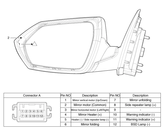
| 1. BSD Indicator | 2. Side repeater lamp |
Repair procedures
| Inspection |
| 1. | Disconnect the negative (-) battery terminal. |
| 2. | Remove the front door trim. (Refer to Body - "Front door trim") |
| 3. | Disconnect the power door mirror connector from the harness
|
| 4. | Check that the mirror operates properly as shown in the below table.
|
| Removal |
| 1. | Disconnect (-) battery terminal. |
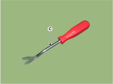
| 2. | Using a fastener remover (C), remove the mirror (A) as illustration below.
|
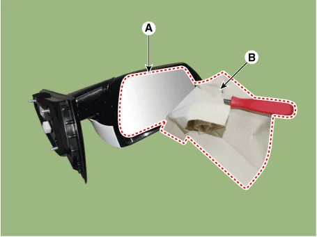

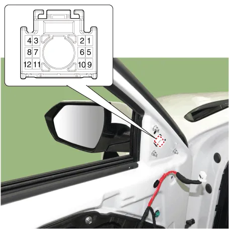
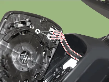
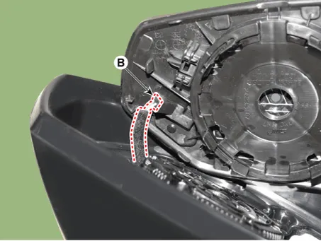
| 3. | Disconnect the mirror heat wire connectors (A) and warning indicator connector (B) and remove the mirror.
|
| Installation |
| 1. | Connect mirror heat wire connector and then install the mirror. |
| 2. | Connect (-) battery terminal then check if mirror works normally. |
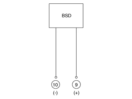
Specifications Specifications Items Blind-Spot Collision Warning (BCW) Blind-Spot Collision- Avoidance Assist-Rear (BCA-R) Rated voltageDC 12VOperating voltage9V - 16VOperating speed30 km/h - 255 km/h60 km/h - 180 km/hSensible distance70m Curvature radiusStart : More than 100mStart : More than 625m Stop : Less than 70mStop : Less than 588m Frequency24 GHzNumbers2EA Items Rear Cross-Traffic Collision Warning (RCCW) Rear Cross-Traffic Collision- Avoidance Assist (RCCA) Rated voltageDC 12VOperating voltage9V - 16VOperating speed0 km/h - 10 km/h1 km/h - 10 km/hSensible distance25mCurvature radius-Frequency24 GHzNumbers2EA Items Safe Exit Assist (SEA) Rated voltageDC 12VOperating voltage9V - 16VOperating speed0 km/h - 3 km/hSensible distance25mCurvature radius-Frequency24GHzNumbers2EA Schematic diagrams Connector and Terminal Function Pin Function 1L-CAN High2C-CAN High3-4Battery (+)5Ground6L-CAN Low7C-CAN Low8Warning indicatorCircuit Diagram Repair procedures Removal lf replacement of the rear corner radar unit bracket or extension wire is required, replace the defective part only with a new one.
Description and operation Description• PDW consists of 8 sensors (front : 4 units, rear : 4 units) that are used to detect obstacles and transmit the result in three separate warning levels, the first, second and third to IBU via LIN communication.
Other information:
Hyundai Elantra (CN7) 2021-2026 Service Manual: Refrigerant Line
Components and components location Components Location1. Refrigerant Pipe Assembly Repair procedures Replacement1.If the compressor is marginally operable, run the engine at idle speed, and let the air conditioning work for a few minutes, then shut the engine off.
Hyundai Elantra (CN7) 2021-2026 Service Manual: Repair procedures
Inspection1.Check for resistance between terminals in each switch position (LH).[LH : Audio + Hands free] Switch Resistance (±5%) SEEK Up430 ΩSEEK Down1.11 kΩMODE2.11 kΩMUTE3.11 kΩVolume (+)4.
Categories
- Manuals Home
- Hyundai Elantra Owners Manual
- Hyundai Elantra Service Manual
- Brake System
- Auto Hold. Warning messages
- Body Electrical System
- New on site
- Most important about car
