Hyundai Elantra (CN7): Engine Control System / CVVD Actuator
Description and operation
| Description |
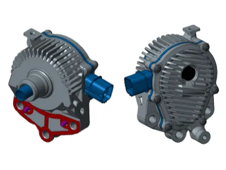
CVVD(Continuous Variable Valve Duration) System is a device to control the optimum open and close timing according to the driving mode by changing the valve opening section.
[CVVD Actuator]
Specifications
| Specification |
|
Item
|
Specification
|
| Type | BLDC MOTOR |
| Operating Voltage (V) | 9.1 - 16 |
| Control Frequency (kHz) | 10 |
Schematic diagrams
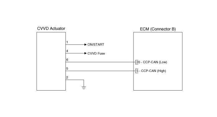
| Circuit Diagram |
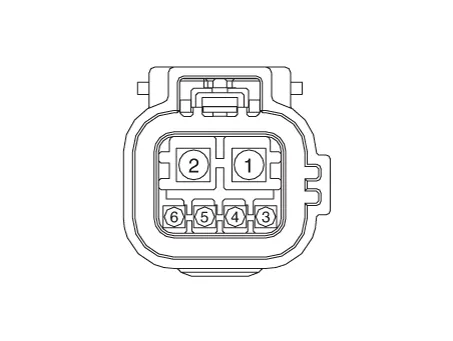
Harness Connector
Repair procedures
| Removal |
| 1. | Turn the ignition switch OFF, and disconnect the battery negative (-) terminal. |
| 2. | Remove the air cleaner assembly. (Refer to Engine Mechanical System - "Air Cleaner Assembly") |
| 3. | Remove the high pressure fuel pipe. (Refer to Fuel Delivery System - "Fuel Line") |
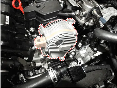
| 4. | Remove the CVVD actuator (A) after loosening the mounting bolt.
|
| Installation |
|


|

| Adjustment |
| 1. | Turn the ignition switch OFF. |
| 2. | Connect the diagnostic tool to Data Link Connector (DLC). |
| 3. | Turn the ignition switch ON. |
| 4. | Select "Vehicle, Model Year, Engine, System". |
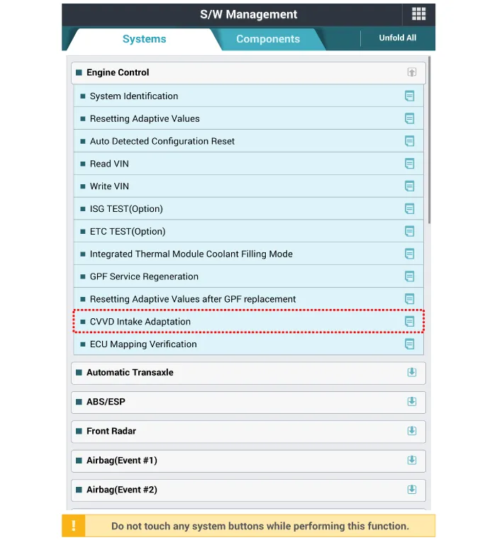
| 5. | Select "CVVD Intake Adaption".
|
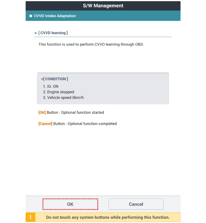
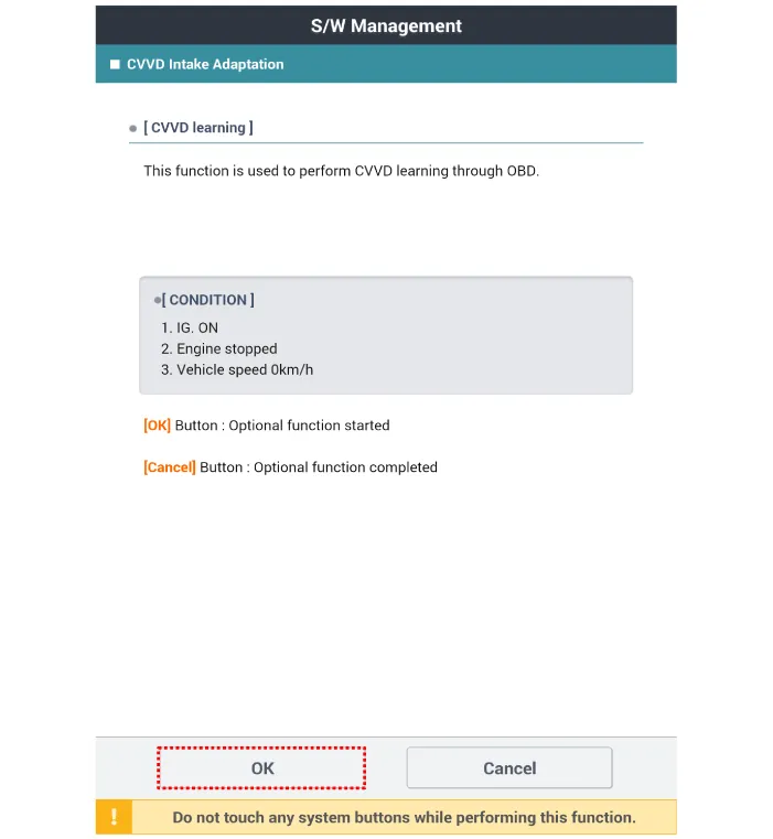
| 6. | Perform the "CVVD Learning" refer to the diagnostic tool.
|
Description and operation DescriptionIntegrated Thermal Management Module (ITM) is a device that controls the coolant flow rate according to coolant temperature.
Other information:
Hyundai Elantra (CN7) 2021-2026 Service Manual: Components and positions
C
Hyundai Elantra (CN7) 2021-2026 Service Manual: Evaporator Core
Repair procedures Replacement1.Disconnect the negative (-) battery terminal. 2.Remove the heater and blower assembly.(Refer to Heater - "Heater Unit") 3.Remove the heater core cover (A) after loosening the mounting screws.4.Pull out the evaporator core (A) from the heater unit.
Categories
- Manuals Home
- Hyundai Elantra Owners Manual
- Hyundai Elantra Service Manual
- Suspension System
- Brake System
- Instrument Panel Overview
- New on site
- Most important about car

Copyright © 2026 www.helantra7.com - 0.0165