Hyundai Elantra (CN7): Blower / Blower Unit
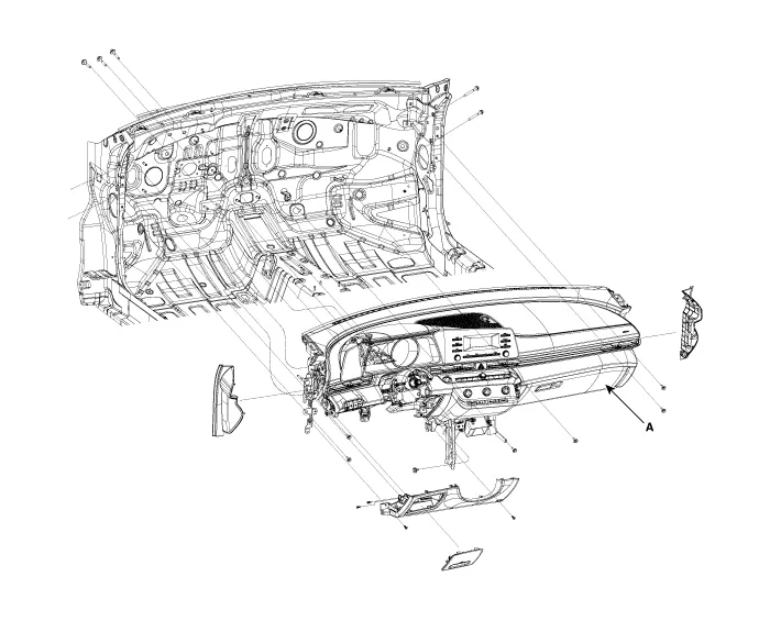
Components and components location
| Component Location |
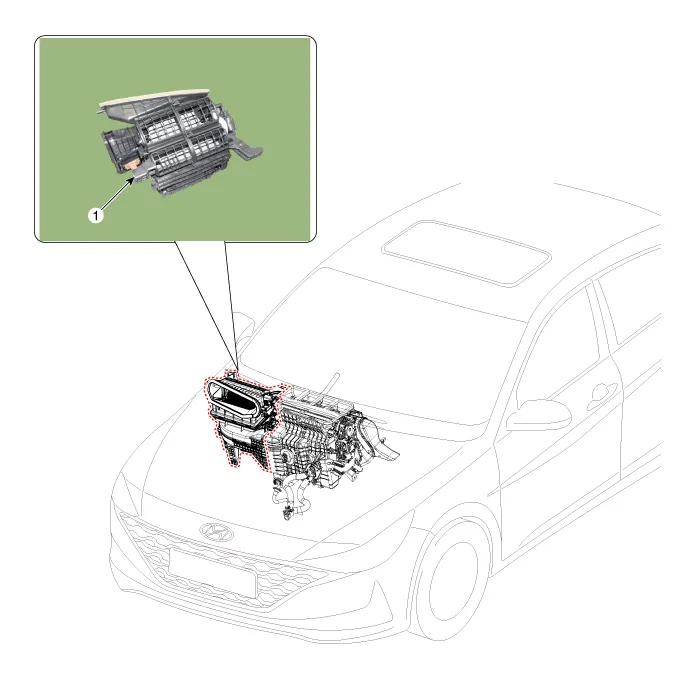
| 1. Blower unit assembly |
| Components |
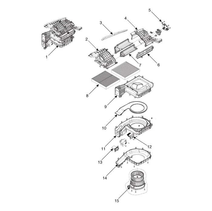
| 1. Blower unit assebmly 2. Blower upper cover [LH] 3. Duct seal 4. Blower upper cover [RH] 5. Intake actuator 6. Air filter cover 7. Intake door | 8. Air filter 9. Blower upper case 10. Blower plate 11. Blower lower case 12. Power mosfet 13. Resistor 14. Blower lower cover 15. Blower motor |
Repair procedures
| Replacement |
| 1. | Disconnect the negative (-) battery terminal. |
| 2. | Recover the refrigerant with a recovery / recycling / charging station. |
| 3. | When the engine is cool, drain the engine coolant from the radiator. (Refer to Engine Mechanical System - "Coolant") |
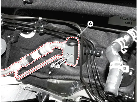
| 4. | Remove the bolts and the expansion valve (A) from the evaporator core.
|

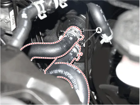
| 5. | Disconnect the heater hoses (A) from the heater unit.
|

| 6. | Remove the cowl top cover. (Refer to Body (Interior and Exterior) - "Cowl Top Cover") |
| 7. | Remove the battery. (Refer to Engine Electrical System - "Battery") |
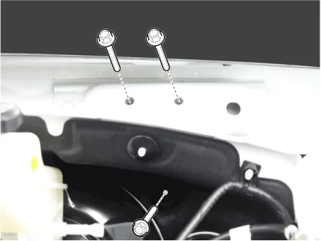
| 8. | Loosen the cowl cross member mounting bolts.
|
| 9. | Remove the front pillar trim. (Refer to Body (Interior and Exterior) - "Front Pillar Trim") |
| 10. | Remove the floor console assembly. (Refer to Body (Interior and Exterior) - "Floor Console Assembly") |
| 11. | Remove the shift lever assembly. (Refer to Automatic Transmission System - "Shift Lever") |
| 12. | Remove the cowl side trim. (Refer to Body (Interior and Exterior) - "Cowl Side Trim") |
| 13. | Remove the crash pad lower panel. (Refer to Body (Interior and Exterior) - "Crash Pad Lower Panel") |
| 14. | Remove the steering column shroud lower panel. (Refer to Body (Interior and Exterior) - "Steering Column Shroud Panel") |
| 15. | Remove the steering wheel. (Refer to Steering System - "Steering Wheel") |
| 16. | Remove the multifunction switch. (Refer to Body Electrical System - "Multifunction Switch") |
| 17. | Lower the steering column after loosening the mounting bolts. (Refer to Steering System - "Steering Column and Shaft") |
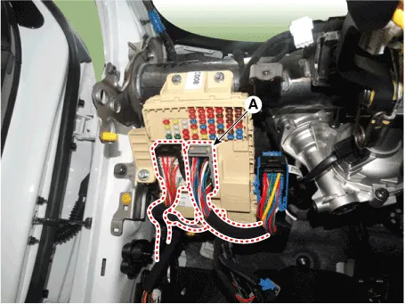
| 18. | Disconnect the junction box connectors (A).
|
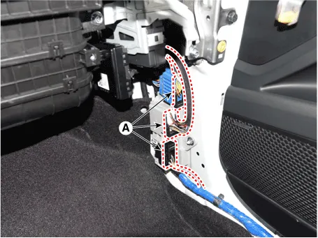
| 19. | Disconnect the multi box connectors (A). [LH]
[RH]
|
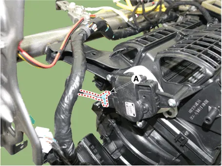
| 20. | Remove the center console duct (A).
|
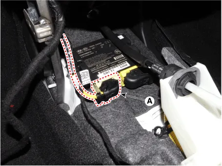
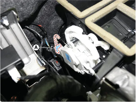
| 21. | Disconnect the airbag control module (SRSCM) connector (A).
|
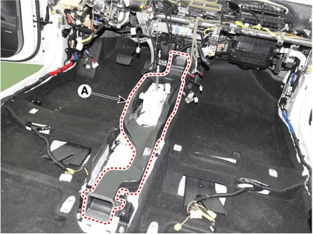
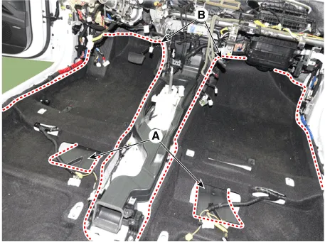
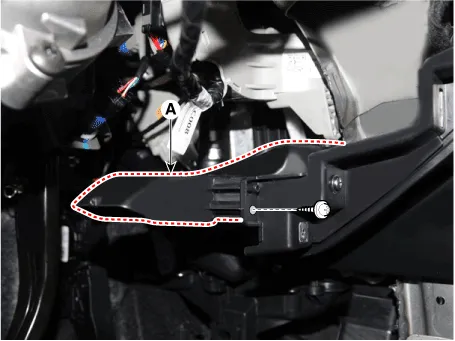
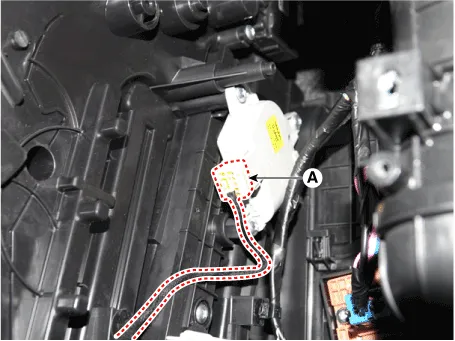
| 22. | Remove the rear air duct (A) and separate the floor carpet (B) to obtain space for removing the rear heating duct.
|
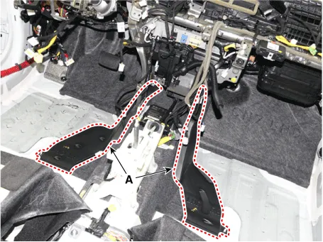
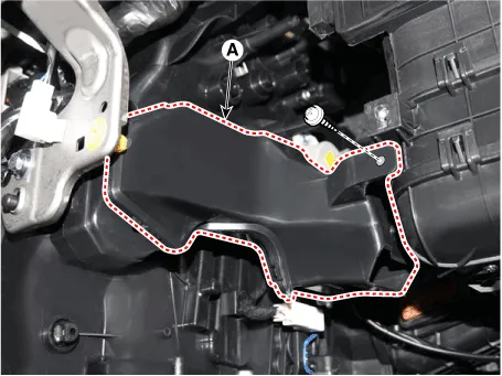
| 23. | Remove the front air duct (A).
|
| 24. | Loosen the cowl blower unit mounting bolts.
|
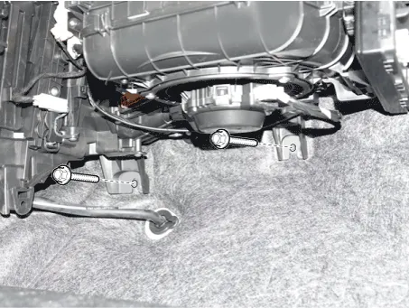
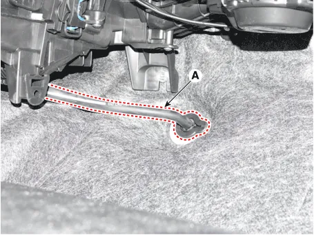
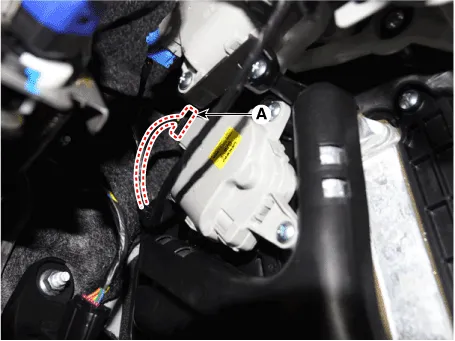
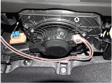
| 25. | Remove the drain hose (A).
|
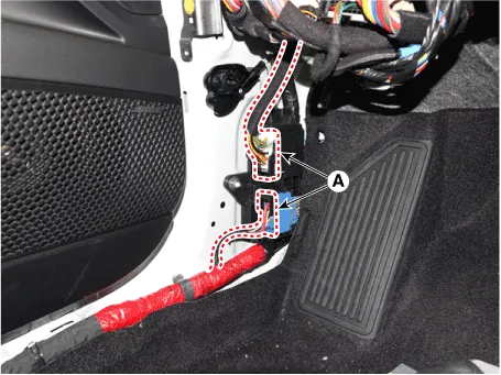
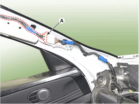
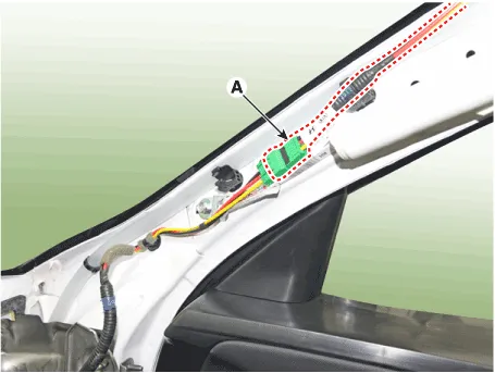
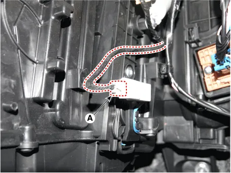
| 26. | Disconnect the connectors (A) and the mounting clips in the front pillar. [LH]
[RH]
|
| 27. | After loosening the bolts and nuts remove the main crash pad and cowl cross bar assembly (A) together.
|
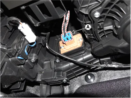
| 28. | Disconnect the heater & blower unit connectors. [Driver
[Passenger's side]
|
| 29. | Loosen the heater & blower unit mounting bolt.
|

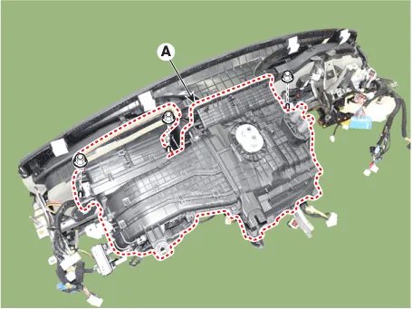
| 30. | Remove the heater and blower unit (A) from the crash pad after loosening the mounting nuts.
|
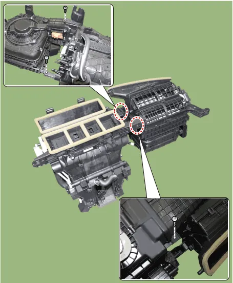
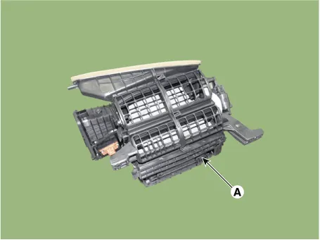
| 31. | Separate the blower unit (A) from the heater & blower unit assembly after loosening the screws.
|
| 32. | To install, reverse the removal procedure. |
Repair procedures Inspection1.Connect the battery voltage and check the blower motor rotation.Replacement1.Disconnect the negative (-) battery terminal.
Other information:
Hyundai Elantra (CN7) 2021-2026 Service Manual: License Lamps
Repair procedures Removal1.Disconnect the negative (-) battery terminal.2.Push the lock pin (B) and remove the license lamp (A).3.Disconnect the license lamp connector (A).4.Replace the bulb (A).Installation1.Connect the license lamp connector.2.Install the license lamp.
Hyundai Elantra (CN7) 2021-2026 Service Manual: Troubleshooting
TroubleshootingWireless Power Charger System Troubleshooting Trouble status Inspection item Inspection Not chargedCheck the mobile phone status R-1Amber LED blinks OvercurrentR-2OverheatingR-2Foreign matterR-2R-1.
Categories
- Manuals Home
- Hyundai Elantra Owners Manual
- Hyundai Elantra Service Manual
- Maintenance
- Vehicle Information
- Body Electrical System
- New on site
- Most important about car

Copyright © 2026 www.helantra7.com - 0.0168