
Hyundai Elantra (CN7): Lighting System / License Lamps
Hyundai Elantra (CN7) 2021-2026 Service Manual / Body Electrical System / Lighting System / License Lamps
Repair procedures
| Removal |
| 1. | Disconnect the negative (-) battery terminal. |
| 2. | Push the lock pin (B) and remove the license lamp (A).
|
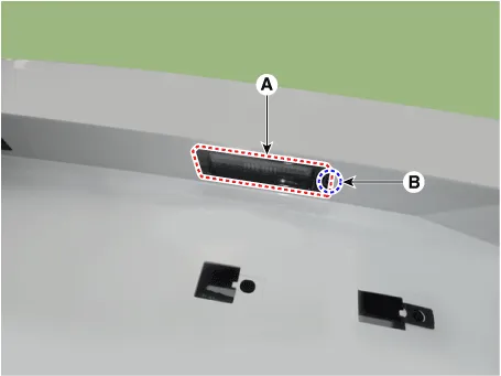
| 3. | Disconnect the license lamp connector (A).
|

| 4. | Replace the bulb (A).
|

| Installation |
| 1. | Connect the license lamp connector. |
| 2. | Install the license lamp. |
| 3. | Connect the negative (-) battery terminal. |
Repair procedures Removal1.Disconnect the negative (-) battery terminal.2.Remove the front bumper.(Refer to Body - "Front Bumper Cover")3.Remove the head lamp.
Repair procedures Removal1.Disconnect the negative (-) battery terminal.2.Remove the rear package tray trim.(Refer to Body - "Rear Package Tray Trim")3.
Other information:
Hyundai Elantra (CN7) 2021-2026 Service Manual: Components and components location
C
Hyundai Elantra (CN7) 2021-2026 Service Manual: Power Mosfet
Description and operation DescriptionIt is installed to the DATC and adjusts the fan rpm by precisely controlling the voltage applied to the blower motor. Repair procedures Inspection1.Manually operate the control switch and measure the voltage of the blower motor.
Categories
- Manuals Home
- Hyundai Elantra Owners Manual
- Hyundai Elantra Service Manual
- Instrument Cluster
- Body Electrical System
- Maintenance
- New on site
- Most important about car

Copyright В© 2026 www.helantra7.com - 0.0229