Hyundai Elantra (CN7): Exhaust Emission Control System / Catalytic Converter
Description and operation
| Description |
Repair procedures
| Removal |
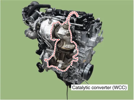
| 1. | Remove the exhaust manifold. (Refer to Engine Mechanical System - "Exhaust Manifold") |
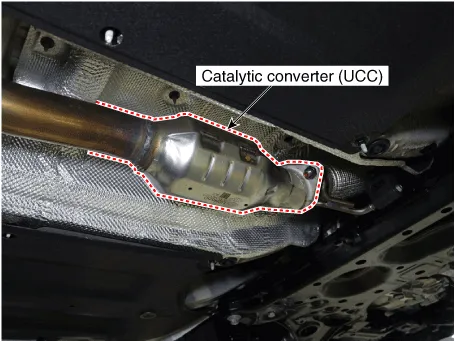
| 1. | Remove the Center Muffler. (Refer to Engine Mechanical System - "Center Muffler") |
| Installation |
| 1. | Install in the reverse order of removal. |
DescriptionExhaust emissions (CO, HC, NOx) are controlled by a combination of engine modifications and the addition of special control components.Modifications to the combustion chamber, intake manifold, camshaft and ignition system form the basic control system.
Description and operation DescriptionContinuous Variable Valve Timing (CVVT) system advances or retards the valve timing of the intake and exhaust valve in accordance with the ECM control signal which is calculated by the engine speed and load.
Other information:
Hyundai Elantra (CN7) 2021-2026 Service Manual: Repair procedures
Refrigerant System Service Basics (R-134a)Refrigerant Recovery Use only service equipment that is U.L-listed and is certified to meet the requirements of SAE J2210 to remove HFC-134a(R-134a) from the air conditioning system. • Air conditioning refrigerant or lubricant vapor can irritate your eyes, nose, or
Hyundai Elantra (CN7) 2021-2026 Service Manual: Heater & A/C Control Unit (Manual)
Components and components location Components[This illustration shows the LHD type. RHD type is symmetrical.][Connector A] Pin No Function Pin No Function 1Low (Register specifications)4Middle Low (Register specifications)2Common (Register
Categories
- Manuals Home
- Hyundai Elantra Owners Manual
- Hyundai Elantra Service Manual
- Repair procedures
- General Tightening Torque Table. General information
- Brake bleeding procedures
- New on site
- Most important about car
