Hyundai Elantra (CN7): AVN System / AVN Antenna
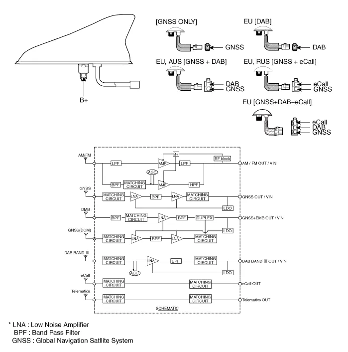
Components and components location
| Components |
Repair procedures
| Removal |
| 1. | Disconnect the negative (-) battery terminal. |
| 2. | Remove the roof trim. (Refer to Body - "Roof Trim Assembly") |
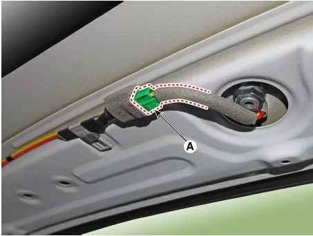
| 3. | Disconnect the roof antenna connector (A).
|
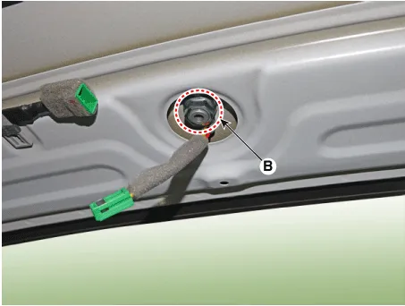
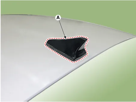
| 4. | Remove the roof antenna (A) after loosening a nut (B).
|
| 1. | Disconnect the negative (-) battery terminal. |
| 2. | Remove the main crash pad assembly. (Refer to Body - "Main Crash Pad Assembly") |
| 3. | Loosen the mounting screws and then remove the crash pad antenna (A).
|

| Installation |
| 1. | Connect the roof antenna connectors. |
| 2. | Install the roof trim assembly.
|

| 1. | Connect the roof antenna connectors and install the roof antenna. |
| 2. | Install the main crash pad assembly. |
Components and components location Components1. Left Remote Control Switch (Audio + Bluetooth)2. Right Remote Control Switch (Cruise + Trip) Schematic diagrams Circuit Diagram[Without paddle shift][With paddle shift][Audio + B/Tooth][Audio + B/Tooth + Voice][Trip][Trip / Cruise][Trip + Cruise + LFA)[Trip + Cruise + LFA + MSLA)[Trip + Smart Cruise + LFA)[Trip + Smart Cruise + LFA + MSLA) Repair procedures Inspection1.
Repair procedures Inspection1.Troubleshooting for Speaker(1)Basic inspection of speakerInspect the sound from speaker after verifying that the speaker mounting screws is removed and the wiring connector is connected precisely to remove vibration transmitted from body trims and surrounding parts.
Other information:
Hyundai Elantra (CN7) 2021-2026 Service Manual: Ignition Switch Assembly. Repair procedures
Repair procedures Replacement1.Disconnect the negative (-) battery terminal.2.Remove the crash pad lower panel.(Refer to Body - "Crash Pad")3.Remove the steering column upper & Lower shroud.4.Remove the ignition switch and disconnecting the Key Warning / immobilizer connector.
Hyundai Elantra (CN7) 2021-2026 Service Manual: Warning Indicator
Components and components location Components1. BSD Indicator2. Side repeater lamp Repair procedures Inspection1.Disconnect the negative (-) battery terminal.2.Remove the front door trim.(Refer to Body - "Front door trim")3.Disconnect the power door mirror connector from the harness4.
Categories
- Manuals Home
- Hyundai Elantra Owners Manual
- Hyundai Elantra Service Manual
- Vehicle Information
- Engine Mechanical System
- Specifications
- New on site
- Most important about car
