Hyundai Elantra (CN7): Manual Transaxle System / Back-up Lamp Switch
Hyundai Elantra (CN7) 2021-2026 Service Manual / Manual Transaxle System / Manual Transaxle System / Back-up Lamp Switch
Description and operation
| Description |
Component location : Control shaft complete
Operation principle : Back up lamp switch is pushed by the reverse lug sliding when select arm, and switches the back up lamp.
Function : Turn on the back up lamp when reversing.
Specifications
| Specification |
|
Item
|
Specification
|
| Current voltage | 12V |
| Working voltage | DC 10~15V |
| Operating force | 3.0kg Max |
| Voltage drop | -0.4V |
| Working temperature | -30°C ~ 100°C [-30°F ~ 212°F] |
Repair procedures
| Inspection |
| 1. | Remove the air cleaner assembly. (Refer to Engine Mechanical System - "Air Cleaner") |
| 2. | Remove the battery and battery tray. (Refer to Engine Electrical System - "Battery") |
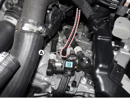
| 3. | Disconnect the back up lamp switch connector (A).
|
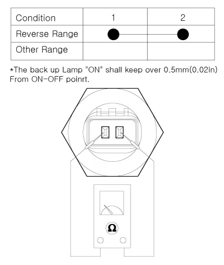
| 4. | Check the continuity between no. 1 and 2 terminals of backup lamp switch. When the shift lever is in reverse, there should be continuity.
|
| Replacement |
| 1. | Remove the air cleaner assembly. (Refer to Engine Mechanical System - "Air Cleaner") |
| 2. | Remove the battery and battery tray. (Refer to Engine Electrical System - "Battery") |
| 3. | Disconnect the back up lamp switch connector (A).
|
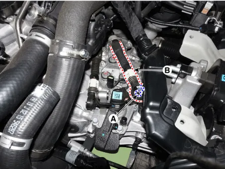
| 4. | Remove the snap pin (A) and then separate the shift cable (B).
|
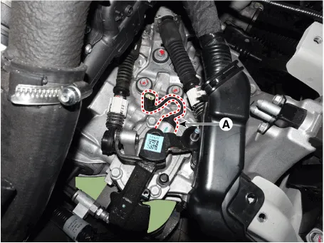
| 5. | Replace the back up lamp switch (A) with a new one.
|
Components and components location Components1. Control shaft complete2. Control cable bracket3. Back-up lamp switch4. Manual transaxle bracket5. Concentric slave cylinder Repair procedures Removal 1.
Other information:
Hyundai Elantra (CN7) 2021-2026 Service Manual: PM Sensor
Description and operation DiscriptionMonitor the air quality inside the vehicle in real time (PM sensor) and display the status on the screen.Automatically operate when fine dust concentration is high (Condition: Bet mode + A/C ON + 3rd speed or higher) Components and components location Components Location1.
Hyundai Elantra (CN7) 2021-2026 Service Manual: Description and operation
D
Categories
- Manuals Home
- Hyundai Elantra Owners Manual
- Hyundai Elantra Service Manual
- General Tightening Torque Table. General information
- Front Bumper
- Front Radar Unit
- New on site
- Most important about car

Copyright © 2026 www.helantra7.com - 0.0138