Hyundai Elantra (CN7): Manual Transaxle System / Manual Transaxle
Components and components location
| Components |
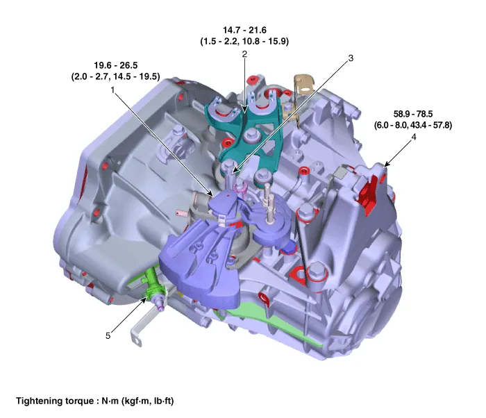
| 1. Control shaft complete 2. Control cable bracket 3. Back-up lamp switch | 4. Manual transaxle bracket 5. Concentric slave cylinder |
Repair procedures
| Removal |
| 1. | Remove the air cleaner assembly and air duct. (Refer to Engine Mechanical System - "Air Cleaner") |
| 2. | Remove the battery and battery tray. (Refer to Engine Electrical System - "Battery") |
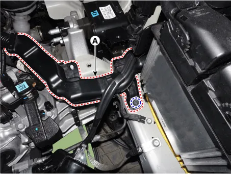
| 3. | Loosen the bolt and then separate the engine wiring (A).
|
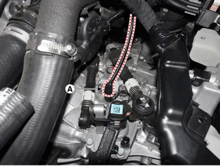
| 4. | Disconnect the back up lamp switch connector (A).
|
| 5. | Remove the control cable bracket and control cable at the same time.
|
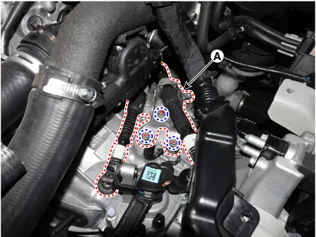
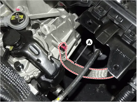
| 6. | Loosen the bolt and then separate the ground line (A).
|
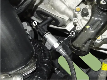
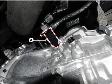
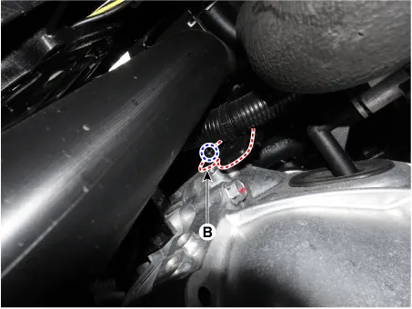
| 7. | Remove the snap pin (A) and the clutch hose (B).
|
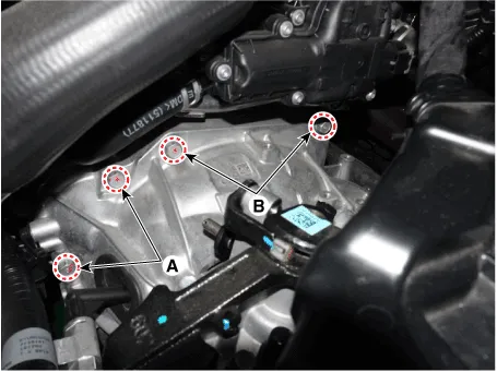
| 8. | Remove the starter motor mounting bolts (A) and the transaxle upper mounting bolts (B).
|
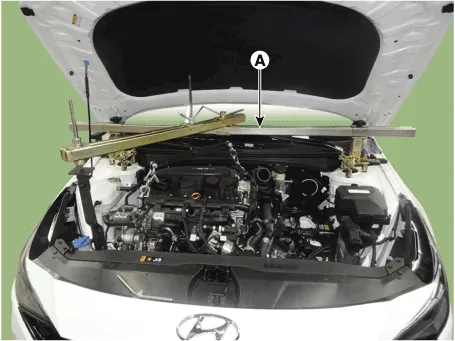
| 9. | Assemble the engine support fixture use a (Beam SST No.: 09200 - 3N000, Adapter SST No.: 09200-4X000, Engine fixture adapter (rear) SST No.: 09200-L1100, Engine fixture adapter (front) SST No.: 09200-L1200. |
| 10. | Using the engine support fixture(A), hold the engine and transaxle assembly safely.
|
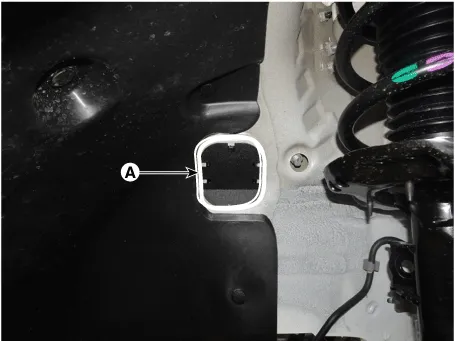
| 11. | Remove the dust cover (A).
|
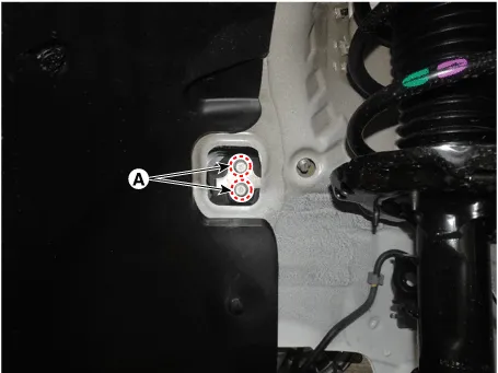
| 12. | Loosen the transaxle bracket support mounting bolts (A).
|
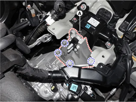
| 13. | Loosen the bolts and then removing the transaxle bracket (A).
|
| 14. | Remove the under cover. (Refer to Engine Mechanical System - "Engine Room Under Cover") |
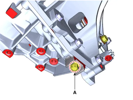
| 15. | After loosening the drain plug (A), drain the manual transaxle fluid, then install the drain plug.
|

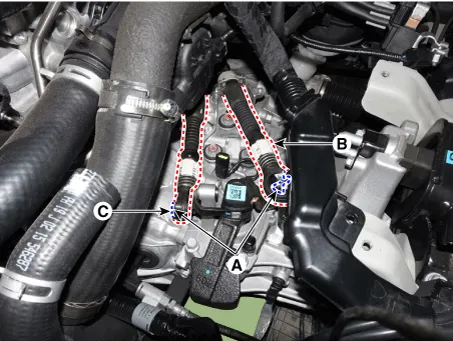
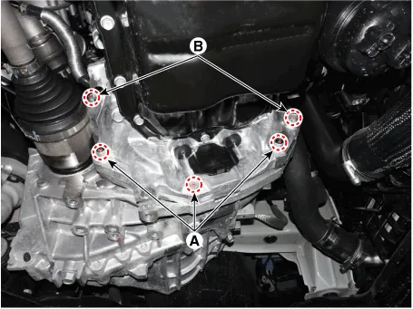
| 16. | Loosen the bolts and then removing the wiring bracket (A, B).
|
| 17. | Loosen the bolts (A, B) and then removing the roll rod assembly (C).
|
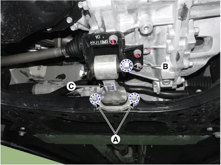
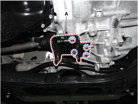
| 18. | Loosen the bolts and then removing the roll rod support bracket (A).
|
| 19. | Remove the drive shaft assembly. (Refer to Driveshaft and axle (2WD-FF) - "Front Driveshaft") |
| 20. | Remove the lower mounting bolts (A), (B) of lower part of the transaxle, and the left side cover and remove the transaxle assembly by supporting it with a jack.
|
| Installation |
|

| 1. | To install, reverse the removal procedures. |
| 2. | Injection the manual transaxle fluid. (Refer to Manual Transaxle System - "Manual Transaxle Fluid") |
| 3. | Perform bleeding air procedure in concentric slave cylinder after pouring the brake fluid. (Refer to Clutch System - "Repair Procedures") |
General information General Information1.Check & Change intervals Check & Replenishment Change Capacity Oil specification Normal use Severe Use 60,000 km / 4 years(40,000 miles / 4years)No service required120,000 km(80,000 miles)1.
Description and operation Description Component location : Control shaft complete Operation principle : Back up lamp switch is pushed by the reverse lug sliding when select arm, and switches the back up lamp.
Other information:
Hyundai Elantra (CN7) 2021-2026 Service Manual: A/C Pressure Transducer
Description and operation DescriptionThe A/C Pressure Transducer (APT) converts the pressure value of high pressure line into voltage value after measuring it. By converted voltage value, engine ECU controls the cooling fan by operating it high speed or low speed.
Hyundai Elantra (CN7) 2021-2026 Service Manual: Rear Corner Radar Unit
Specifications Specifications Items Blind-Spot Collision Warning (BCW) Blind-Spot Collision- Avoidance Assist-Rear (BCA-R) Rated voltageDC 12VOperating voltage9V - 16VOperating speed30 km/h - 255 km/h60 km/h - 180 km/hSensible distance70m Curvature radiusStart : More
Categories
- Manuals Home
- Hyundai Elantra Owners Manual
- Hyundai Elantra Service Manual
- Drive Mode
- Integrated Thermal Management Module (ITM)
- Driver assistance system
- New on site
- Most important about car
