Hyundai Elantra (CN7): Cooling System / Cooling Fan
Components and components location
| Components |
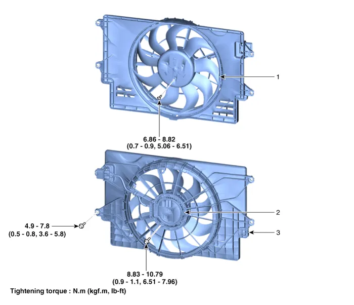
| 1. Cooling fan 2. Fan motor | 3. Cooling fan shroud |
Repair procedures
| Removal and Installation |
Cooling Fan Assembly
| 1. | Disconnect the negative battery terminal. |
| 2. | Remove the air duct and air cleaner assembly. (Refer to Intake and Exhaust System - "Air Cleaner") |
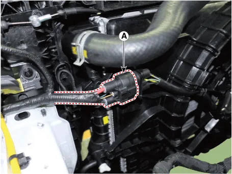
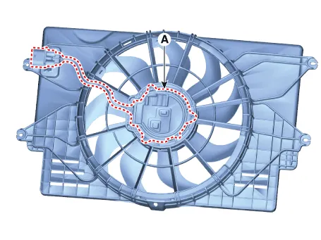
| 3. | Disconnect the cooling fan connector (A).
|
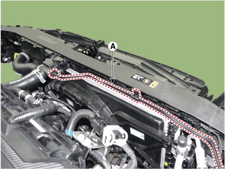
| 4. | Disconnect the degassing hose (A) and hose fastener.
|
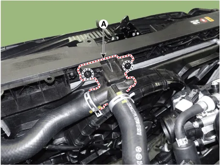
| 5. | Remove the filler neck assembly (A).
|
| 6. | Remove the cooling fan (A) from the radiator.
|

| 7. | Install in the reverse order of removal. |
| Disassembly |
| 1. | Remove the cooling fan (A) from the cooling fan assembly.
|

| 2. | Remove the fan motor (A) from the cooling fan shroud.
|
| 3. | Install in the reverse order of removal. |
| Inspection |
Fan motor
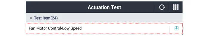
| 1. | Turn ignition switch "OFF" and connect the diagnostic tool to the Data Link Connector. |
| 2. | With the gear shift in P (Park) position and ignistion switch "ON" (LED of the Power button illuminates in Red), select the "force drive" function. |
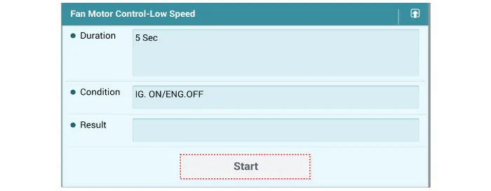
| 3. | Force drive the cooling fan motor.
|
Repair procedures Removal and Installation1.Drain the coolant.(Refer to Cooling System - "Coolant")2.Disconnect the degassing hose (A) and coolant reservoir tank hose (B).
Components and components location Components1. Radiator2. Radiator upper hose3. Radiator lower hose4. Filler neck assembly 5. Radiator upper mounting bracket6.
Other information:
Hyundai Elantra (CN7) 2021-2026 Service Manual: Components and components location
C
Hyundai Elantra (CN7) 2021-2026 Service Manual: ADAS Parking ECU (ADAS_PRK)
Components and components location Components and Components Location Repair procedures Removal • Use a plastic panel removal tool to remove interior trim pieces without marring the surface.• Take care not to bend or scratch the trim and panels.
Categories
- Manuals Home
- Hyundai Elantra Owners Manual
- Hyundai Elantra Service Manual
- General Tightening Torque Table. General information
- Driver assistance system
- Troubleshooting
- New on site
- Most important about car

Copyright © 2026 www.helantra7.com - 0.0196