
Hyundai Elantra (CN7): Cooling System / Radiator
Components and components location
| Components |
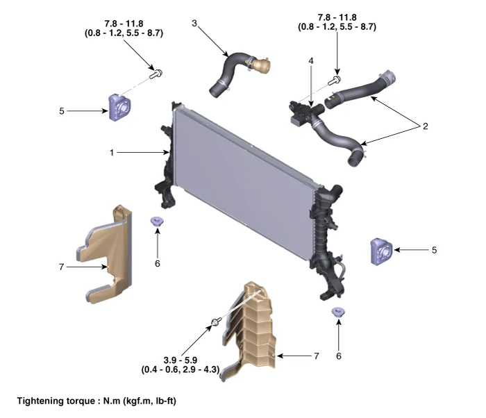
| 1. Radiator 2. Radiator upper hose 3. Radiator lower hose 4. Filler neck assembly | 5. Radiator upper mounting bracket 6. Radiator lower mounting insulator 7. Radiator air guard |
Repair procedures
| Removal and Installation |
| 1. | Disconnect the battery negative terminal. |
| 2. | Remove the engine room under cover. (Refer to Engine and Transaxle Assembly - "Engine Room Under Cover") |
| 3. | Drain the coolant. (Refer to Cooling System - "Coolant") |
| 4. | Remove the cooling fan assembly. (Refer to Cooling System - "Cooling Fan") |
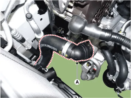
| 5. | Disconnect the radiator lower hose (A).
|
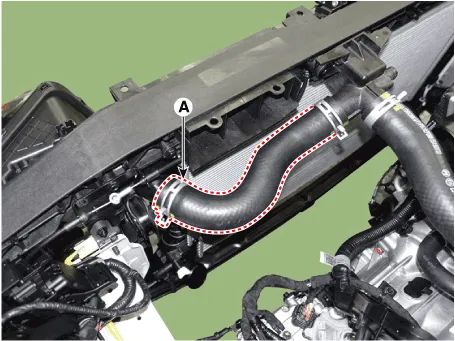
| 6. | Disconnect the radiator upper hose (A)
|
| 7. | Remove the front bumper. (Refer to Body (Interior and Exterior) - "Front Bumper") |
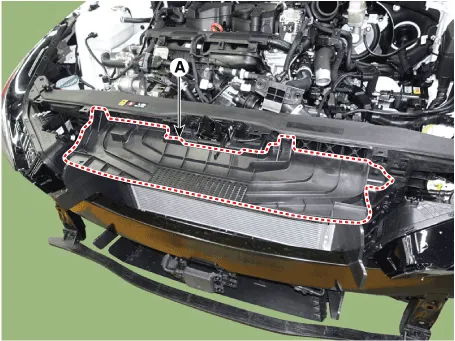
| 8. | Remove the air guard (A).
|
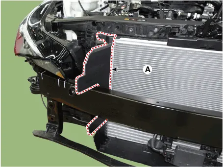
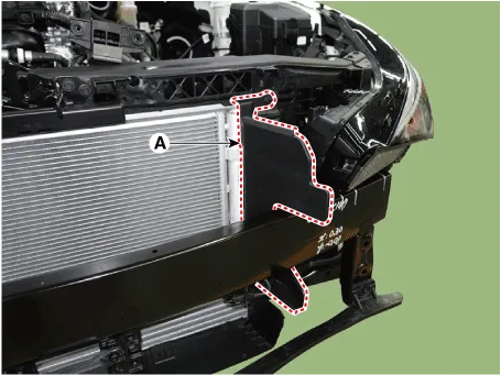
| 9. | Remove the side air guard (A).
[RH]
[LH]
|
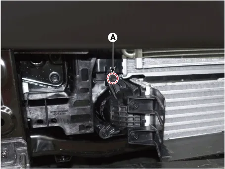
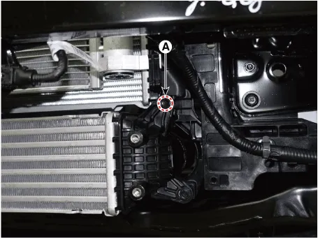
| 10. | Loosen the intercooler mounting bolts (A).
[RH]
[LH]
|
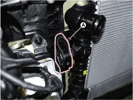
| 11. | Remove the radiator upper mounting bracket bolts (A).
[RH]
[LH]
|

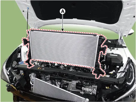
| 12. | Separate the A/C condenser from the radiator and then remove the radiator (A) from the vehicle.
|
| 13. | Install in the reverse order of removal. |
| 14. | Fill with engine coolant. (Refer to Cooling System - "Coolant")
|

| 15. | Start engine and check for leaks. |
| Inspection |
| 1. | Wait for the engine to cool. Carefully remove the coolant reservoir tank cap and fill the radiator with engine coolant. Then, install it on the pressure tester. |
| 2. | Apply a pressure tester to the radiator and apply a pressure of 125.3 - 154.7 kPa (1.28 - 1.58 kgf/cm², 22.44 - 18.17 psi). |
| 3. | Inspect for engine coolant leaks and a drop in pressure. |
| 4. | Remove the tester and reinstall the radiator cap.
|
Components and components location Components1. Cooling fan2. Fan motor3. Cooling fan shroud Repair procedures Removal and InstallationCooling Fan Assembly1.
Components and components location Components1. Integrated thermal management module (ITM)2. Heater pipe3. Heater hose4. Turbo charger coolant hose5.
Other information:
Hyundai Elantra (CN7) 2021-2026 Service Manual: Mood Lamp
Repair procedures RemovalMood lamp unit1.Disconnect the negative (-) battery terminal.2.Remove the main crash pad assembly.(Refer to Body - "Main Crash Pad Assembly")3.Loosen the mounting screws and remove the main crash pad air duct (A).4.Loosen the mounting screws and remove the mood lamp unit (A).
Hyundai Elantra (CN7) 2021-2026 Service Manual: General safety information and caution
General Safety Information and Caution1.Be careful when driving the vehicle using the smart cruise control system as follows.(1)On curves or inclines/declines• The smart cruise control system may have limits to detect distance to the vehicle ahead due to road and traffic conditions.
Categories
- Manuals Home
- Hyundai Elantra Owners Manual
- Hyundai Elantra Service Manual
- Vehicle Information
- Function settings
- Drive Mode
- New on site
- Most important about car
