Hyundai Elantra (CN7): Cooling System / Integrated Thermal Management Module (ITM)
Components and components location
| Components |
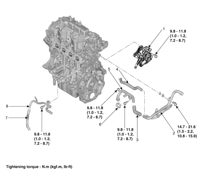
| 1. Integrated thermal management module (ITM) 2. Heater pipe 3. Heater hose 4. Turbo charger coolant hose | 5. Heater pipe A 6. Heater pipe A gasket 7. Oil cooler hose A 8. Oil cooler pipe |
Description and operation
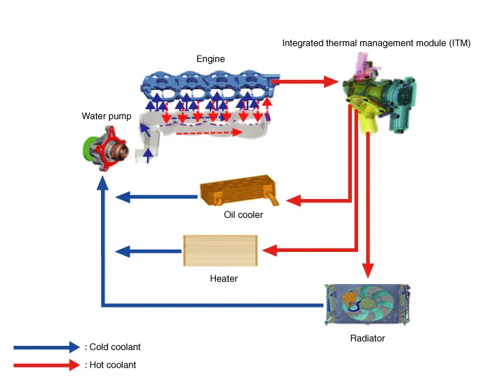
| Description |
Repair procedures
| Removal and Installation |
|

| 1. | Disconnect the battery negative terminal. |
| 2. | Remove the engine room under cover. (Refer to Engine and Transaxle Assembly - "Engine Room Under Cover") |
| 3. | Drain the coolant. (Refer to Cooling System - "Coolant") |
| 4. | Remove the air duct and air cleaner assembly. (Refer to Intake and Exhaust System - "Air Cleaner") |
| 5. | Remove the battery. (Refer to Engine Electrical System - "Battery") |
| 6. | Remove the battery tray. (Refer to Engine Electrical System - "Battery") |
| 7. | Disconnect the integrated thermal management module (ITM) connector (A).
|
| 8. | Disconnect the intercooler inlet hose (A).
|
| 9. | Remove the intercooler pipe (A).
|
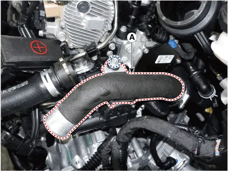
| 10. | Disconnect the radiator upper hose (A).
|
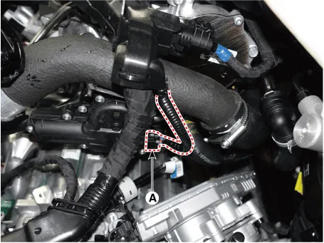
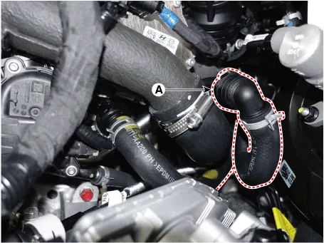
| 11. | Disconnect the heater hose (A).
|
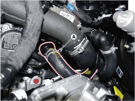
| 12. | Disconnect the oil cooler hose (A).
|
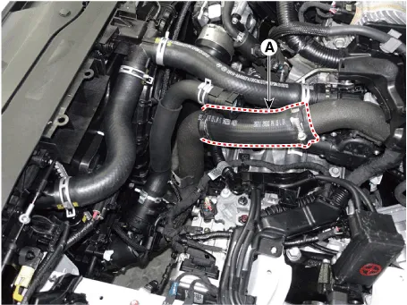
| 13. | Remove the integrated thermal management module (ITM) (A).
|

| 14. | Install in the reverse order of removal. |
| 15. | Fill with engine coolant. (Refer to Cooling System - "Coolant")
|
| 16. | Start engine and check for leaks. |
| 1. | Disconnect the battery negative terminal. |
| 2. | Remove the engine cover. (Refer to Engine and Transaxle Assembly - "Engine Cover") |
| 3. | Remove the engine room under cover. (Refer to Engine and Transaxle Assembly - "Engine Room Under Cover") |
| 4. | Drain the coolant. (Refer to Cooling System - "Coolant") |
| 5. | Remove the air duct and air cleaner assembly. (Refer to Intake and Exhaust System - "Air Cleaner") |
| 6. | Remove the battery. (Refer to Engine Electrical System - "Battery") |
| 7. | Remove the battery tray. (Refer to Engine Electrical System - "Battery") |
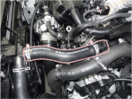
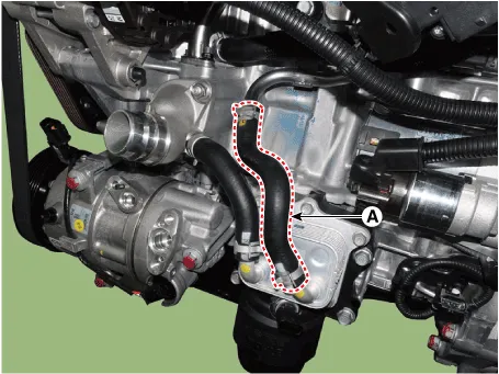
| 8. | Disconnect the heater hoses (A).
|
| 9. | Remove the integrated thermal management module (ITM). |
| 10. | Remove the intake manifold. (Refer to Intake and Exhaust System - "Intake Manifold") |
| 11. | Remove the drive belt. (Refer to Drive Belt System - "Drive Belt") |
| 12. | Remove the alternator. (Refer to Engine Electrical System - "Alternator") |
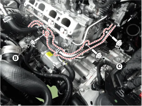
| 13. | Disconnect the wiring connectors and harness clamps and remove the connector brackets around the heater pipe. |
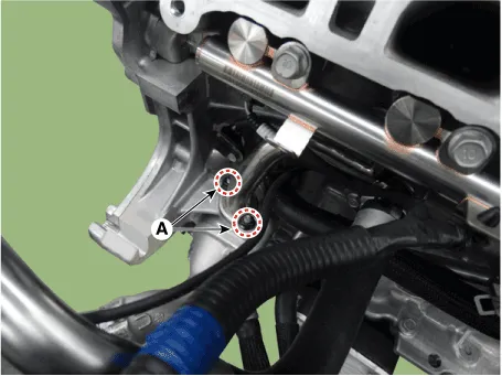
| 14. | Remove the heater pipe B mounting nuts (A)
|
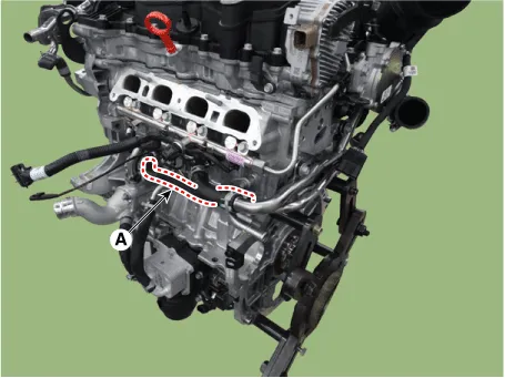
| 15. | Disconnect the heater outlet pipe hose (A).
|
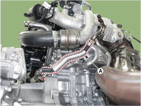
| 16. | Disconnect the turbo charger coolant hose A (A).
|
| 17. | Remove the heater pipe A and heater pipe B (A).
|
| 18. | Install in the reverse order of removal.
|
| 19. | Fill with engine coolant. (Refer to Cooling System - "Coolant")
|
| 20. | Start engine and check for leaks. |
| 1. | Remove the heater pipe |
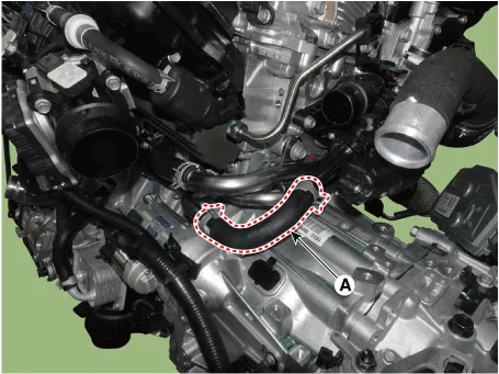
| 2. | Disconnect the cooler hose (A).
|
| 3. | Disconnect the cooler hose (A).
|
| 4. | Rmove the oil cooler pipe (A) after loosening the mounting bolts.
|

| 5. | Install in the reverse order of removal. |
| 6. | Fill with engine coolant. (Refer to Cooling System - "Coolant")
|
| 7. | Start engine and check for leaks. |
Components and components location Components1. Radiator2. Radiator upper hose3. Radiator lower hose4. Filler neck assembly 5. Radiator upper mounting bracket6.
Repair procedures RemovalWater Inlet Fitting1.Remove the engine room under cover.(Refer to Engine and Transaxle Assembly - "Engine Room Under Cover")2.
Other information:
Hyundai Elantra (CN7) 2021-2026 Service Manual: Antenna Coil
Repair procedures Removal1.Disconnect the negative (-) battery terminal.2.Remove the crash pad lower panel.(Refer to Body - "Crash Pad Lower Panel")3.Remove the steering column shroud panel.(Refer to Body - "Steering Column Shroud Panel")4.Disconnect the immobilizer connector (A) and press the locking pin (B) using an awl.
Hyundai Elantra (CN7) 2021-2026 Service Manual: Condenser
Components and components location Components Location[General type]1. Condenser[N Line]1. Condenser Repair procedures Inspection1.Check the condenser fins for clogging and damage. If clogged, clean them with water, and blow them with compressed air.
Categories
- Manuals Home
- Hyundai Elantra Owners Manual
- Hyundai Elantra Service Manual
- Engine Control / Fuel System
- Instrument Panel Overview
- General Tightening Torque Table. General information
- New on site
- Most important about car
