Hyundai Elantra (CN7): Driver Parking Assistance System / ADAS Parking ECU (ADAS_PRK)
Components and components location
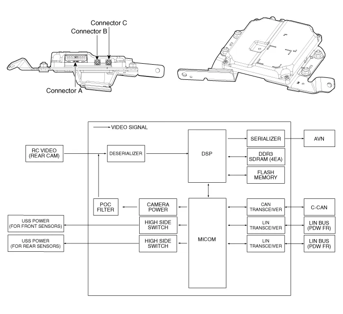
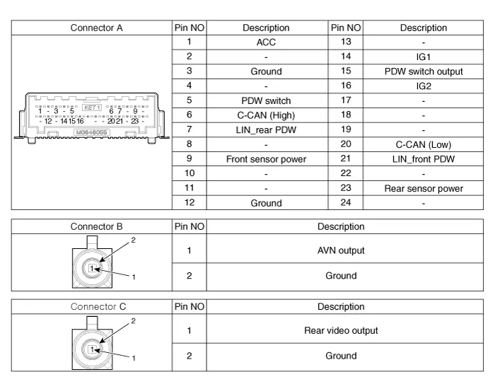
| Components and Components Location |
Repair procedures
| Removal |
|

| 1. | Disconnect the negative (-) battery terminal. |
| 2. | Remove the AVN Head unit. (Refer to Body Electrical System - "AVN Head Unit") |
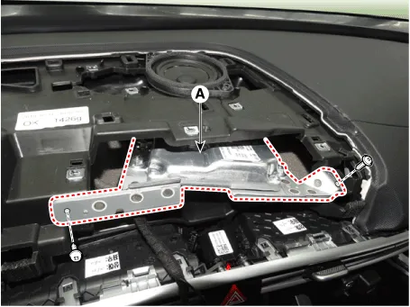
| 3. | Loosen the mounting screws and remove the ADAS_PRK Unit (A).
|
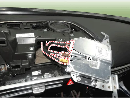
| 4. | Disconnect the ADAS_PRK Unit connectors (A).
|
| Installation |
| 1. | Install in the reverse order of removal. |
| 2. | Connect the cable of Diagnostic tool to the data link connector in driver side crash pad lower panel, and turn on the Diagnostic tool. |
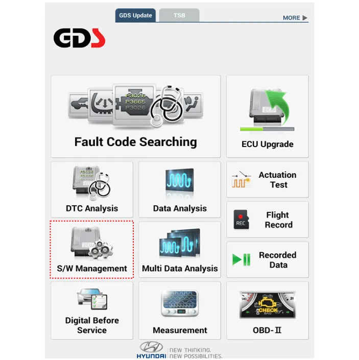
| 3. | Select the 'S/W Management' and 'Car model'.
|
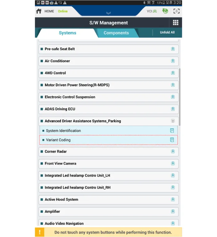
| 4. | Select the 'Advanced Driver Assistance Systems_Parking' and Variant Coding.
|
TroubleshootingDiagnosis with Diagnostic tool1.In the body electrical system, failure can be quickly diagnosed by using the vehicle diagnostic system (Diagnostic tool).
Components and components location Components and Components Location Schematic diagrams Schematic DiagramsParking Collision-Avoidance Assist (PCA) Ultrasonic sensorParking Collision-Avoidance Assist (PCA) Rear view camera Repair procedures RemovalParking Collision-Avoidance Assist (PCA) Unit1.
Other information:
Hyundai Elantra (CN7) 2021-2026 Service Manual: Evaporator Core
Repair procedures Replacement1.Disconnect the negative (-) battery terminal. 2.Remove the heater and blower assembly.(Refer to Heater - "Heater Unit") 3.Remove the heater core cover (A) after loosening the mounting screws.4.Pull out the evaporator core (A) from the heater unit.
Hyundai Elantra (CN7) 2021-2026 Service Manual: Heater & A/C Control Unit (Manual)
Components and components location Components[This illustration shows the LHD type. RHD type is symmetrical.][Connector A] Pin No Function Pin No Function 1Low (Register specifications)4Middle Low (Register specifications)2Common (Register
Categories
- Manuals Home
- Hyundai Elantra Owners Manual
- Hyundai Elantra Service Manual
- Brake System
- Integrated Thermal Management Module (ITM)
- Rear Seats
- New on site
- Most important about car
