Hyundai Elantra (CN7): Cooling System / Water Inlet Fitting
Repair procedures
| Removal |
| 1. | Remove the engine room under cover. (Refer to Engine and Transaxle Assembly - "Engine Room Under Cover") |
| 2. | Drain the coolant. (Refer to Cooling System - "Coolant") |
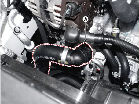
| 3. | Disconnect the radiator lower hose (A).
|
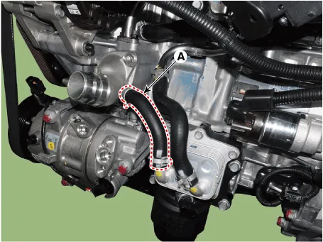
| 4. | Disconnect the oil cooler hose (A).
|
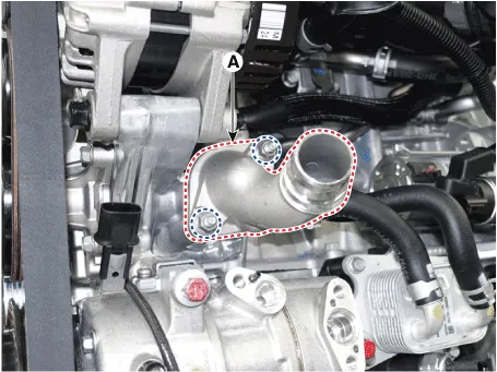
| 5. | Remove the water inlet fitting (A).
|
| 6. | Install in the reverse order of removal.
|

| 7. | Fill with engine coolant. (Refer to Cooling System - "Coolant")
|
| 8. | Start engine and check for leaks. |
Components and components location Components1. Integrated thermal management module (ITM)2. Heater pipe3. Heater hose4. Turbo charger coolant hose5.
Components and components location Components1. Water pump pulley2. Water pump 3. Water pump gasket Repair procedures Removal1.Remove the engine room under cover.
Other information:
Hyundai Elantra (CN7) 2021-2026 Service Manual: Ignition Switch Assembly. Repair procedures
Repair procedures Replacement1.Disconnect the negative (-) battery terminal.2.Remove the crash pad lower panel.(Refer to Body - "Crash Pad")3.Remove the steering column upper & Lower shroud.4.Remove the ignition switch and disconnecting the Key Warning / immobilizer connector.
Hyundai Elantra (CN7) 2021-2026 Service Manual: Troubleshooting
TroubleshootingDiagnosis with Diagnostic tool1.In the body electrical system, failure can be quickly diagnosed by using the vehicle diagnostic system (Diagnostic tool).The diagnostic system (Diagnostic tool) provides the following information.1)Fault Code Searching : Checking failure and code number (DTC)2)Data Analysis : Checking the system input/
Categories
- Manuals Home
- Hyundai Elantra Owners Manual
- Hyundai Elantra Service Manual
- Vehicle Information
- General Tightening Torque Table. General information
- Specifications
- New on site
- Most important about car
