Hyundai Elantra (CN7): Cylinder Block / Cylinder Block
Repair procedures
| Disassembly |
|

|

| 1. | Remove the crankshaft. (Refer to Cylinder Block - "Crankshaft") |
| 2. | Remove the water jacket insert. (Refer to Cylinder Block - "Water Jacket Insert") |
| 3. | Remove the knock sensor. (Refer to Engine Control / Fuel System - "Knock Sensor (KS)") |
| 4. | Remove the crankshaft position sensor (CKPS). (Refer to Engine Control / Fuel System - "Crankshaft Position Sensor (CKPS)") |
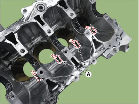
| 5. | Remove the piston cooling oil jets (A).
|
| Inspection |
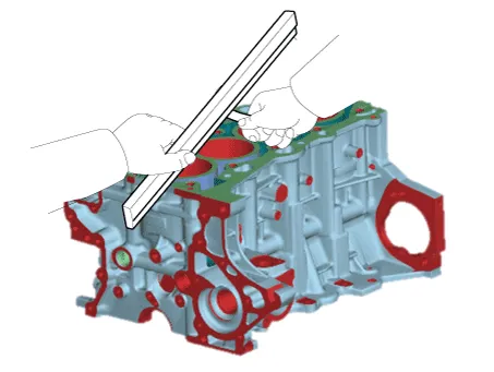
| 1. | Using a gasket scraper, remove all the gasket material from the top surface of the cylinder block. |
| 2. | Using a soft brush and solvent, thoroughly clean the cylinder block. |
| 3. | Inspect the top surface of cylinder block for flatness. Using a precision straight edge and feeler gauge, measure the surface contacting the cylinder head gasket for warpage.
|
| 4. | Visually check for scratches on the inside surface of the cylinder bore and replace the cylinder block if any noticeable scratch is detected. If deep scratchs are present, replace the cylinder block. |
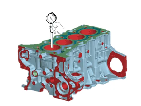
| 5. | Using the cylinder bore gauge, measure the cylinder bore’s inner diameter to the axial and axial perpendicular directions.
|
| Reassembly |
|
| 1. | Install the piston cooling oil jets (A).
|
| 2. | Install the crankshaft. (Refer to Cylinder Block - "Crankshaft") |
| 3. | Check the crankshaft end play. (Refer to Cylinder Block - "Crankshaft") |
| 4. | Disconnect the lower crankcase and check crankshaft bearing oil clearance. (Refer to Cylinder Block - "Crankshaft") |
| 5. | Install the piston and connecting rod assembly. (Refer to Cylinder Block - "Piston and Connecting Rod") |
| 6. | Check the connecting rod bearing cap oil clearance. (Refer to Cylinder Block - "Piston and Connecting Rod") |
| 7. | Check the connecting rod end play. (Refer to Cylinder Block - "Piston and Connecting Rod") |
| 8. | Assemble the other parts in the reverse order of disassembly.
|
Repair procedures Disassembly • Use fender covers to avoid damaging painted surfaces.• To avoid damage, unplug the wiring connectors carefully while holding the connector portion.
Other information:
Hyundai Elantra (CN7) 2021-2026 Service Manual: Mood Lamp
Repair procedures RemovalMood lamp unit1.Disconnect the negative (-) battery terminal.2.Remove the main crash pad assembly.(Refer to Body - "Main Crash Pad Assembly")3.Loosen the mounting screws and remove the main crash pad air duct (A).4.Loosen the mounting screws and remove the mood lamp unit (A).
Hyundai Elantra (CN7) 2021-2026 Service Manual: Heater & A/C Control Unit (DATC)
Components and components location Components[This illustration shows the LHD type. RHD type is symmetrical.][Connector A] Pin No Function Pin No Function 1Battery9IGN22ILL+ (TAIL)10ISG Battery (+)3-11IGN14LIN BUS12HTD5-13-6-14-7-15-8RHEO (
Categories
- Manuals Home
- Hyundai Elantra Owners Manual
- Hyundai Elantra Service Manual
- Engine Control / Fuel System
- Vehicle Information
- Specifications
- New on site
- Most important about car
