Hyundai Elantra (CN7): Driveshaft Assembly / Dynamic Damper
Repair procedures
| Removal |
| 1. | Remove the front drive shaft. (Refer to Driveshaft Assembly - "Front Driveshaft") |
| 2. | Remove the trans axle side joint. (Refer to Driveshaft Assembly - "Transaxl Joint") |
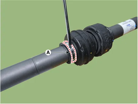
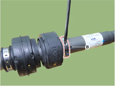
| 3. | Remove the dynamic damper band (A, B) using driver (-).
|

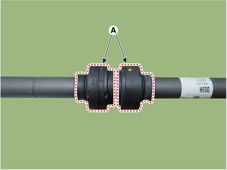
| 4. | Remove the dynamic damper (A).
|
| Installation |
| 1. | Install the dynamic damper (A).
|
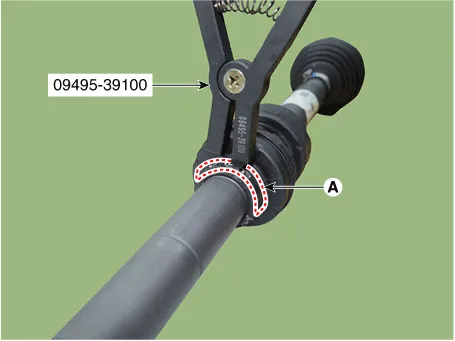
| 2. | Install the dynamic damper band (A) using SST (09495-39100).
|
| 3. | Install the transaxle side joint. (Refer to Driveshaft Assembly - "Transaxl Joint") |
| 4. | Install the front driveshaft. (Refer to Driveshaft Assembly - "Front Driveshaft") |
Components and components location Components1. Driveshaft (LH)2. Dynamic damper3. Driveshaft (RH) Repair procedures Removal1.Loosen the wheel nuts slightly.
Repair procedures Removal • Drive shaft joints require special grease, so do not add any other type of grease.
Other information:
Hyundai Elantra (CN7) 2021-2026 Service Manual: Description and operation
DescriptionThe immobilizer system will disable the vehicle unless the proper ignition key is used, in addition to the currently available anti-theft systems such as car alarms, the immobilizer system aims to drastically reduce the rate of auto theft.1.
Hyundai Elantra (CN7) 2021-2026 Service Manual: Blower Unit
Components and components location Component Location1. Blower unit assemblyComponents1. Blower unit assebmly2. Blower upper cover [LH]3. Duct seal4. Blower upper cover [RH]5. Intake actuator6. Air filter cover7. Intake door8. Air filter9. Blower upper case10.
Categories
- Manuals Home
- Hyundai Elantra Owners Manual
- Hyundai Elantra Service Manual
- General Tightening Torque Table. General information
- Driver assistance system
- Front Radar Unit
- New on site
- Most important about car
