Hyundai Elantra (CN7): Driveshaft Assembly / Front Driveshaft
Components and components location
| Components |
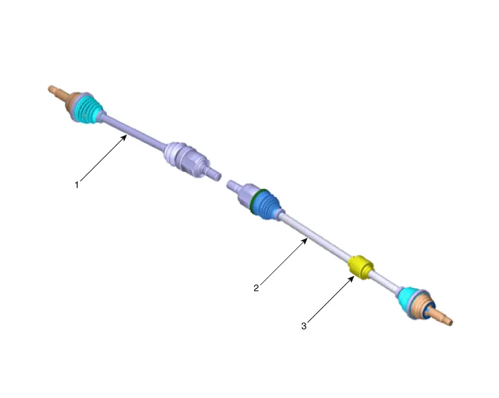
| 1. Driveshaft (LH) 2. Dynamic damper | 3. Driveshaft (RH) |
Repair procedures
| Removal |
| 1. | Loosen the wheel nuts slightly. Raise the vehicle, and make sure it is securely supported. |
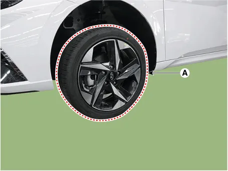
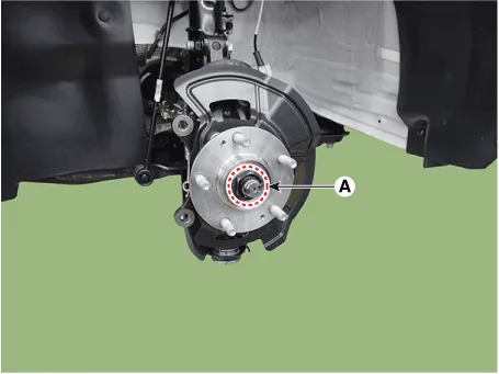
| 2. | Remove the front wheel and tire (A) from the front hub.
|

| 3. | Remove the front brake caliper. (Refer to Brake System - "Front Disc Brake") |
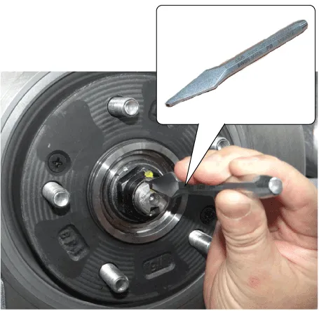
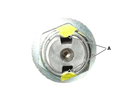
| 4. | By hammering on a chisel, unlock the driveshaft lock hub nut caulking.
|
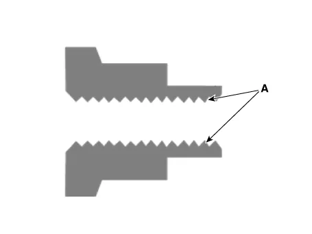
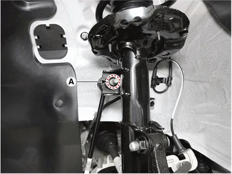
| 5. | Loosen the driveshaft caulking nut (A) from the front hub.
|

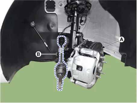
| 6. | Remove the stabilizer link from the front strut after loosening the mounting nut.
|
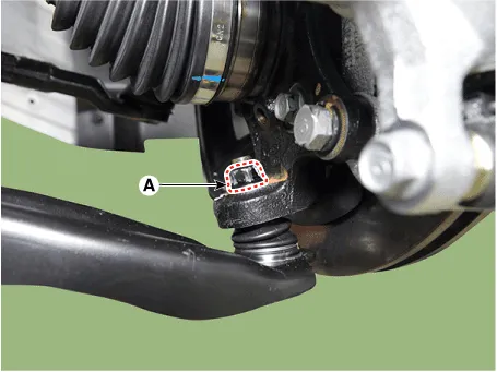
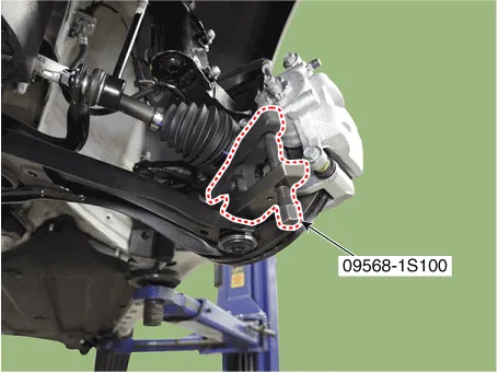
| 7. | Separate the lower arm ball joint by using the SST (09568-1S100) after loosening the lower arm mounting nut (A).
|
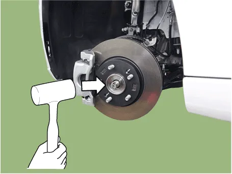
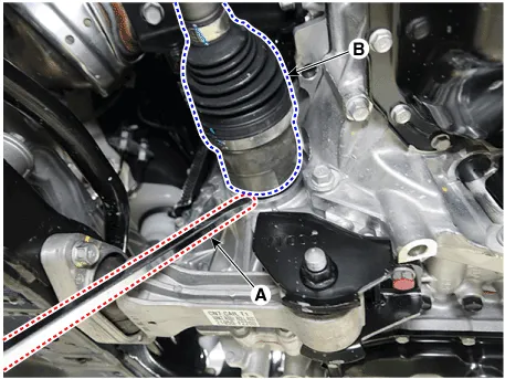
| 8. | Separate the front knuckle (A) from the front drive shaft (B) by using the plastic hammer.
|
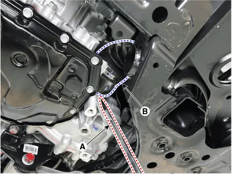
| 9. | Remove the front drive shaft (B) by using the pry bar (A).
[LH]
[RH]
|
| Installation |
| 1. | To install, reverse the removal procedures. |
| 2. | Check the alignment. (Refer to Suspension System - "Alingment") |
Repair procedures Removal1.Remove the front drive shaft.(Refer to Driveshaft Assembly - "Front Driveshaft")2.Remove the trans axle side joint.(Refer to Driveshaft Assembly - "Transaxl Joint")3.
Other information:
Hyundai Elantra (CN7) 2021-2026 Service Manual: Auto Lighting Control System
Description and operation DescriptionIt's a system that uses illumination sensor to automatically turn ON the tail lamp and head lamp based on the change in surrounding environment's illumination condition. It activates when the vehicle enters/exits tunnel, or when the illumination condition in surrounding environment changes due to rain, snow, or
Hyundai Elantra (CN7) 2021-2026 Service Manual: Troubleshooting
TroubleshootingDiagnosis with Diagnostic tool1.In the body electrical system, failure can be quickly diagnosed by using the vehicle diagnostic system (Diagnostic tool).The diagnostic system (Diagnostic tool) provides the following information.1)Fault Code Searching : Checking failure and code number (DTC)2)Data Analysis : Checking the system input/
Categories
- Manuals Home
- Hyundai Elantra Owners Manual
- Hyundai Elantra Service Manual
- Body (Interior and Exterior)
- Vehicle Information
- Drive Mode
- New on site
- Most important about car
