
Hyundai Elantra (CN7): Front Seat / Front Seat Back Cover
Components and components location
| Component Location |
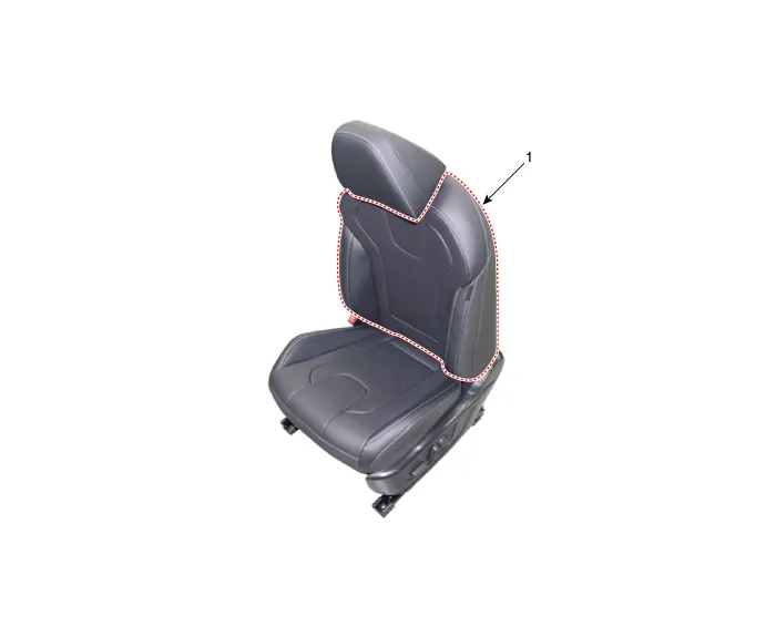
| 1. Front seat back cover |
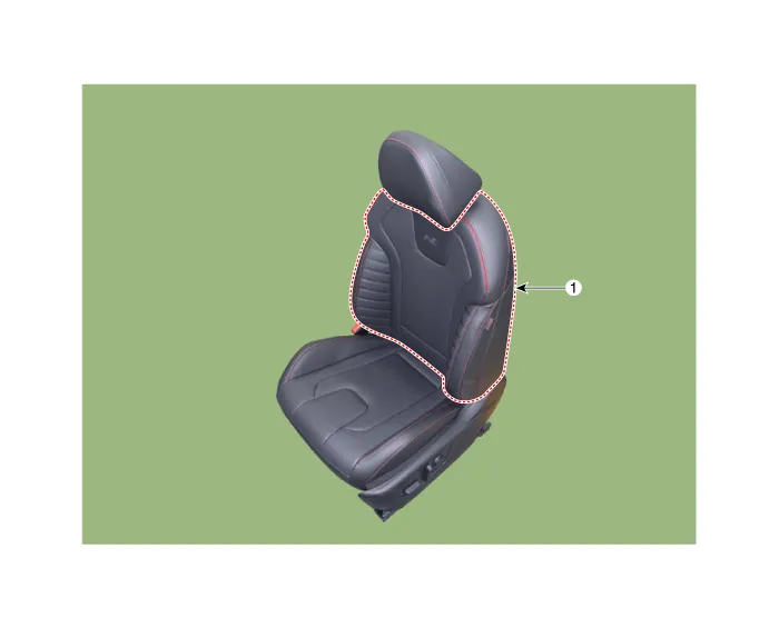
| 1. Front seat back cover |
Repair procedures
| Replacement |
|

| 1. | Remove the front seat assembly. (Refer to Front Seat - "Front Seat Assembly") |
| 2. | Remove the front seat headrest (A) by pulling it upward.
|

| 3. | Remove the front seat lower protector (A).
|
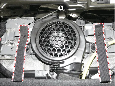
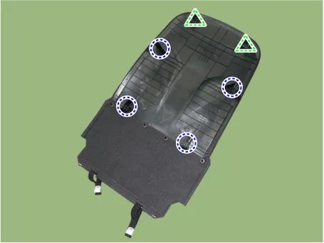
| 4. | Remove the front seat back board (A).
|

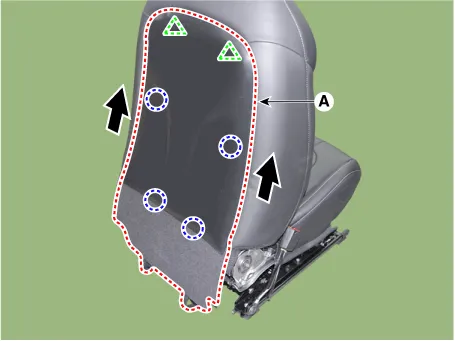
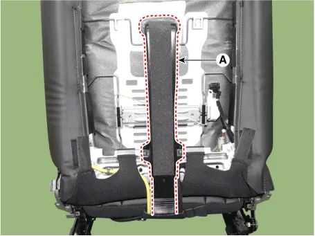
| 5. | Disconnect the front seat ventilation duct (A).
|
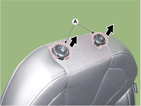
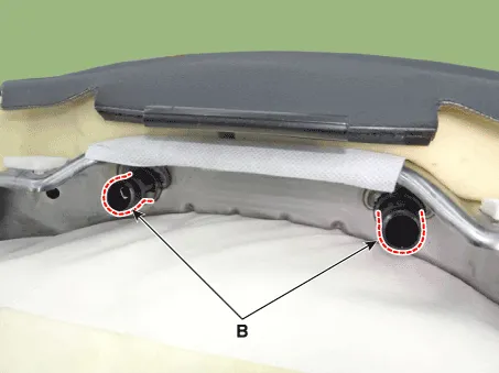
| 6. | Press the both hook (B) and remove the headrest guides (A) by pulling upward.
|
| 7. | Press the lock pin, separate the lock pin (A).
|
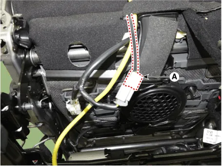
| 8. | Separate the front seat back cover protector, remove the front seat back cover (A).
|
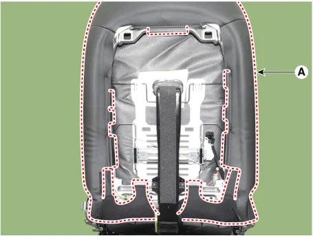
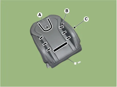
| 9. | Remove the velcro tape (A) and tie down clips (B) inside the front seat back cover and remove the seat back cover (C).
|
| 10. | Install in the reverse order of removal.
|

Components and components location Component Location[General type]1. Front seat shield inner cover[N Line]1. Front seat shield inner cover Repair procedures Replacement • When removing with a flat-tip screwdriver or remover, wrap protective tape around the tools to prevent damage to components.
Components and components location Component Location[General type]1. Front seat cushion cover [N Line]1. Front seat cushion cover Repair procedures Replacement • When removing with a flat-tip screwdriver or remover, wrap protective tape around the tools to prevent damage to components.
Other information:
Hyundai Elantra (CN7) 2021-2026 Service Manual: In-car Sensor
Description and operation DescriptionThe In-car air temperature sensor is built in the heater & A/C control unit.The sensor contains a thermistor which measures the temperature of the inside. The signal decided by the resistance value which changes in accordance with perceived inside temperature, is delivered to heater control unit and accor
Hyundai Elantra (CN7) 2021-2026 Service Manual: Troubleshooting
TroubleshootingDiagnosis with Diagnostic tool1.In the body electrical system, failure can be quickly diagnosed by using the vehicle diagnostic system (Diagnostic tool).The diagnostic system (Diagnostic tool) provides the following information.1)Fault Code Searching : Checking failure and code number (DTC)2)Data Analysis : Checking the system input/
Categories
- Manuals Home
- Hyundai Elantra Owners Manual
- Hyundai Elantra Service Manual
- Rear Seats
- Driver assistance system
- Body Electrical System
- New on site
- Most important about car
