Hyundai Elantra (CN7): Blind-Spot Collision Warning (BCW) / Limitations of the function
Blind-Spot Safety system may not operate normally, or the system may operate unexpectedly under the following circumstances:
- There is inclement weather, such as heavy snow, heavy rain, etc.
- The rear corner radar is covered with snow, rain, dirt, etc.
- The temperature around the rear corner radar is high or low
- Driving on a highway (or motorway) ramp
- The road pavement (or the peripheral ground) abnormally contains metallic components (i.e. possibly due to subway construction)
- There is a fixed object near the vehicle, such as sound barriers, guardrails, central dividers, entry barriers, street lamps, signs, tunnels, walls, etc. (including double structures)
- Driving in large areas where there are few vehicles or structures (i.e. desert, meadow, suburb, etc.)
- Driving through a narrow road where trees or grass are overgrown
- Driving on a wet road surface, such as a puddle on the road
- The other vehicle drives very close behind your vehicle, or the other vehicle passes by your vehicle in close proximity
- The speed of the other vehicle is very fast that it passes by your vehicle in a short time
- Your vehicle passes by the other vehicle
- Your vehicle changes lane
- Your vehicle has started at the same time as the vehicle next to you and has accelerated
- The vehicle in the next lane moves two lanes away from you, or when the vehicle two lanes away moves to the next lane from you
- A trailer or carrier is installed around the rear corner radar
- The bumper around the rear corner radar is covered with objects, such as a bumper sticker, bumper guard, bike rack, etc.
- The bumper around the rear corner radar is impacted, damaged or the radar is out of position
- Your vehicle height is low or high due to heavy loads, abnormal tire pressure, etc.
Blind-Spot Safety system may not operate normally, or the system may operate unexpectedly when the following objects are detected:
- A motorcycle or bicycle is detected
- A vehicle such as a flat trailer is detected
- A big vehicle such as a bus or truck is detected
- A moving obstacle such as a pedestrian, animal, shopping cart or a baby stroller is detected
- A vehicle with low height such as a sports car is detected
WARNING
• Driving on a curve
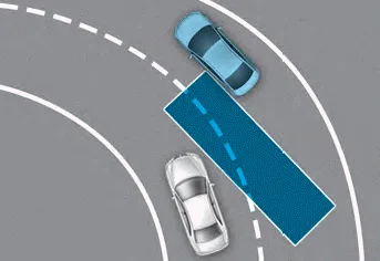
Blind-Spot Safety system may not operate properly when driving on a curved road. The system may not detect the vehicle in the next lane.
Always pay attention to road and driving conditions while driving.
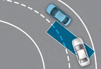
Blind-Spot Safety system may not operate properly when driving on the curved road. The system may recognize the vehicle in the same lane.
Always pay attention to road and driving conditions while driving.
• Driving where the road is merging/ dividing
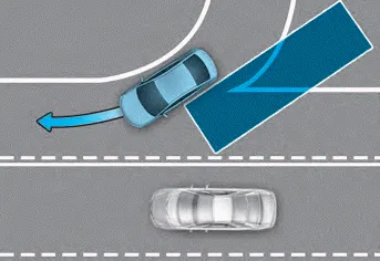
Blind-Spot Safety system may not operate properly when driving where the road merges or divides. The system may not detect the vehicle in the next lane.
Always pay attention to road and driving conditions while driving.
• Driving on a slope
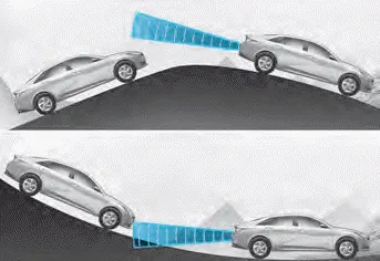
Blind-Spot Safety system may not operate properly when driving on a slope. The system may not detect the vehicle in the next lane or may incorrectly detect the ground or structure.
Always pay attention to road and driving conditions while driving.
• Driving where the heights of the lanes are different
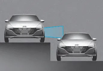
Blind-Spot Safety system may not operate properly when driving where the heights of the lanes are different. The system may not detect the vehicle on a road with different lane heights (underpass joining section, grade separated intersections, etc.).
Always pay attention to road and driving conditions while driving.
WARNING
- When you are towing a trailer or another vehicle, make sure that you turn off Blind-Spot Safety system.
- Blind-Spot Safety system may not operate normally if interfered by strong electromagnetic waves.
- Blind-Spot Safety system may not operate for 15 seconds after the vehicle is started, or the rear corner radars are initialized.
When the rear bumper around the rear corner radar or sensor is covered with foreign material, such as snow or rain, or installing a trailer or carrier, it can reduce the detecting performance and temporarily limit or disable Blind-Spot Safety system.
Blind-Spot Collision-Avoidance Assist is designed to help detect and monitor approaching vehicles in the driver’s blind spot area and warn the driver of a possible collision with a warning message and audible warning.
Other information:
Hyundai Elantra (CN7) 2021-2026 Service Manual: Components and components location
C
Hyundai Elantra (CN7) 2021-2026 Service Manual: Blower Resistor (Manual)
Repair procedures Inspection1.Measure the resistance between the terminals.2.The measured resistance is not within specification, the blower resistor must be replaced. (After removing the resistor)Replacement1.Disconnect the negative (-) battery terminal.
Categories
- Manuals Home
- Hyundai Elantra Owners Manual
- Hyundai Elantra Service Manual
- Vehicle Information
- Front Radar Unit
- Drive Mode
- New on site
- Most important about car
