Hyundai Elantra (CN7): Immobilizer System / Repair procedures
| Diagnosis with Diagnostic tool |
| 1. | In the body electrical system, failure can be quickly diagnosed by using the vehicle diagnostic system (Diagnostic tool). The diagnostic system (Diagnostic tool) provides the following information. | (1) | Fault Code Searching : Checking failure and code number (DTC) |
| (2) | Data Analysis : Checking the system input/output data state |
| (3) | Actuation test : Checking the system operation condition |
| (4) | S/W Management : Controlling other features including system option setting and zero point adjustment |
|
Data Analysis
| 1. | Select the 'Data Analysis' and 'Car model'. 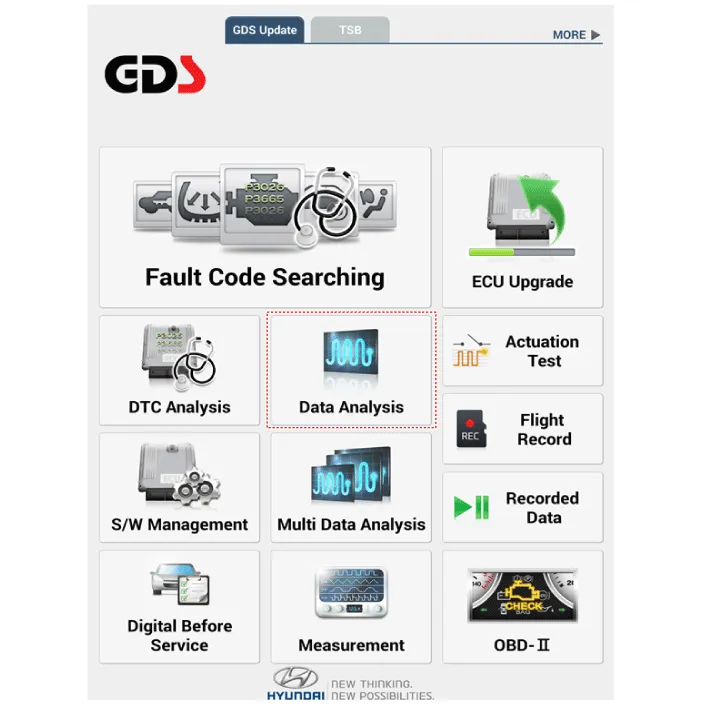
|
| 2. | Select the 'IMMO' to search the current state of the input/output data. 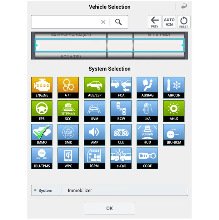
|
Key Teaching Procedure
Key teaching must be done after replacing a defective PCM(ECM) or when providing additional keys to the vehicle owner.
The procedure starts with an PCM(ECM) request for vehicle specific data (PIN code: 6digits) from the tester. The "virgin" PCM(ECM) stores the vehicle specific data and the key teaching can be started. The "learnt" PCM(ECM) compares the vehicle specific data from the tester with the stored data. If the data are correct, the teaching can proceed.
If incorrect vehicle specific data have been sent to the PCM(ECM) three times, the PCM(ECM) will reject the request of key teaching for one hour. This time cannot be reduced by disconnecting the battery or any other manipulation. After reconnecting the battery, the timer starts again for one hour.
The key teaching is done by ignition on with the key and additional tester commands. The PCM(ECM) stores the relevant data in the EEPROM and in the transponder. Then the PCM(ECM) runs the authentication required for confirmation of the teaching process. The successful programming is then confirmed by a message to the tester.
If the key is already known to the PCM(ECM) from a previous teaching, the authentication will be accepted and the EEPROM data are updated. There is no changed transponder content (this is impossible for a learnt transponder).
The attempt to repeatedly teach a key, which has been taught already during the same teaching cycle, is recognized by the PCM(ECM). This rejects the key and a message is sent to the tester.
The PCM(ECM) rejects invalid keys, which are presented for teaching. A message is sent to the tester. The key can be invalid due to faults in the transponder or other reasons, which result from unsuccessful programming of data. If the PCM(ECM) detects different authenticators of a transponder and an PCM(ECM), the key is considered to be invalid.
The maximum number of taught keys is 4.
If an error occurs during the Immobilizer Service Menu, the PCM(ECM) status remains unchanged and a specific fault code is stored.
If the PCM(ECM) status and the key status do not match for teaching of keys, the tester procedure will be stopped and a specific fault code will be stored at PCM(ECM).
| •
| When teaching the 1st key, Smartra regists at the same time. |
|

The following section describes how to diagnose faults using a diagnostic instrument.
| 1. | Connect the cable of Diagnostic tool to the data link connector in driver side crash pad lower panel, and turn on the Diagnostic tool. |
| 2. | Select the 'S/W Management' and 'Car model'. 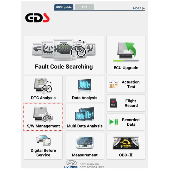
|
| 3. | Select "Imoobilizer" and "LEARNT KEYS". 
|
| 4. | Perform the "LEARNT KEYS" procedure according to the Diagnostic tool screen message. |
Password Teaching / Changing
The user password for limp home is taught at the service station. The owner of the vehicle can select a number with four digits.
The user password teaching is only accepted by a "learnt" PCM(ECM). Before first teaching of user password to an PCM(ECM), the status of the password is "virgin" No limp home function is possible.
The teaching is started by ignition on, with a valid key(learnt key) and sending the user password by tester. After successful teaching, the status of the user password changes from "virgin" to "learnt".
The learnt user password can also be changed. This can be done if the user password status is "learnt" and the tester sends authorization of access, either the old user password or the vehicle specific data. After correct authorization, the PCM(ECM) requests the new user password. The status remains "learnt" and the new user password will be valid for the next limp home mode.
If wrong user passwords or wrong vehicle specific data have been sent to the PCM(ECM) three times continuously or intermittently, the PCM(ECM) will reject the request to change the password for one hour. This time cannot be reduced by disconnecting the battery or any other actions. After reconnecting the battery, the timer starts again for one hour.
The following section describes how to diagnose faults using a diagnostic instrument.
| 1. | Connect the cable of Diagnostic tool to the data link connector in driver side crash pad lower panel, and turn on the Diagnostic tool. |
| 2. | Select the 'S/W Management' and 'Car model'.
|
| 3. | Select "Imoobilizer" and "Password Teaching / Changing". 
|
| 4. | Perform the "Password Teaching / Changing" procedure according to the Diagnostic tool screen message. |
Limp Home Function
If the PCM(ECM) detects the fault of the SMARTRA or transponder, the PCM(ECM) will allow limp home function of the immobilizer. Limp home is only possible if the user password (4 digits) has been given to the PCM(ECM) before. This password can be selected by the vehicle owner and is programmed at the service station.
The user password can be sent to the PCM(ECM) via the special tester menu.
Only if the PCM(ECM) is in status "learnt" and the user password status is "learnt" and the user password is correct, the PCM(ECM) will be unlocked for a period of time (30 sec.). The engine can only be started during this time. After the time has elapsed, engine start is not possible.
If the wrong user password is sent, the PCM(ECM) will reject the request of limp home for one hour. Disconnecting the battery or any other action cannot reduce this time. After connecting the battery to the PCM(ECM), the timer starts again for one hour.
| 1. | Connect the cable of Diagnostic tool to the data link connector in driver side crash pad lower panel, and turn on the Diagnostic tool. |
| 2. | Select the 'S/W Management' and 'Car model'.
|
| 3. | Select "Imoobilizer" and "Limp Home Mode". 
|
| 4. | Perform the "Limp Home Mode" procedure according to the Diagnostic tool screen message. |
Neutralizing Of ECM
The PCM(ECM) can be set to the "neutral" status by a tester.
A valid ignition key is inserted and after ignition on is recorded, the PCM(ECM) requests the vehicle specific data from the tester. The communication messages are described at "Neutral Mode" After successfully receiving the data, the PCM(ECM) is neutralized.
The ECM remains locked. Neither the limp home mode nor the "twice ignition on" function, is accepted by the PCM(ECM).
The teaching of keys follows the procedure described for the virgin PCM(ECM). The vehicle specific data have to be unchanged due to the unique programming of the transponder. If data should be changed, new keys with a virgin transponder are requested.
This function is for neutralizing the PCM(ECM) and Key. Ex) when lost key, Neutralize the PCM(ECM) then teach keys.
(Refer to the Things to do when Key & PIN Code the PCM(ECM) can be set to the "neutral" status by a scanner. If wrong vehicle specific data have been sent to SMATRA three times continuously or intermittently, the SMATRA will reject the request to enter neutral mode for one hour. Disconnecting the battery or other manipulation cannot reduce this time. After connecting the battery the timer starts again for one hour.
| •
| Neutralizing setting condition - In case of PCM(ECM) status "Learnt" regardless of user password "Virgin or Learnt" - Input correct PIN code by scanner. - Neutralizing meaning . : PIN code (6) & user password (4) deletion. : Locking of ECM (except key teaching permission) |
| •
| Neutralizing meaning: - PIN Code(6) & User P/Word(4) deletion - Locking of EMS(except Key Learning permission) |
|
| 1. | Connect the cable of Diagnostic tool to the data link connector in driver side crash pad lower panel, and turn on the Diagnostic tool. |
| 2. | Select the 'S/W Management' and 'Car model'.
|
| 3. | Select "Imoobilizer" and "Limp Home Mode". 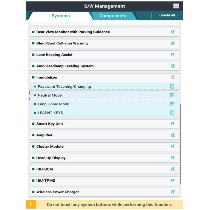
|
| 4. | Perform the "Limp Home Mode" procedure according to the Diagnostic tool screen message. |
DescriptionThe immobilizer system will disable the vehicle unless the proper ignition key is used, in addition to the currently available anti-theft systems such as car alarms, the immobilizer system aims to drastically reduce the rate of auto theft.
Components and components location
Components (1)With Smart KeyConnector Pin Information
Pin no
Connector A
Connector B
Connector C
Connector D
Connector E
1ESCL (+)_output----2Front heated nozzle_output----3-Puddle pocket lamp_output-Mirror folding_output-4Front washer switch _Input---5-LIN(PDW)--ESCL enable_output6Ground_PowerR-PDW power_input--RPM_input7Ground_ECUR-PDW power_output--Start relay_output8ESCL (-)_outputF-PDW power_output--ACC relay_output9Battery (+) ECUATM solenoid_output-Auto light sensor ground_outputStart feedback_input10Battery (+) PowerHead lamp high beam switch_input-Rear view camera switch_inputSSB switch2_input11IGN_InputFront washer switch _Input-R-PDW switch_inputTrunk antenna (-)_output12Kiline_IMMOFront wiper INT volume switch_input-P-Position_inputInterior2 antenna power(-)_output13-Wiper parking switch_input-Passenger outside handle switch_input-14-External buzzer_output-Multifunction Switch ground _InputPassenger outside handle antenna (-)_output15-R-PDW switch IND_output-ACC_input-16---IGN2_input-17--Front wiper low back up switch_input-18--Brake switch_inputDriver outside handle antenna (-)_output19---Immobilizer antenna ground_output20----21----22LIN 3(Rain sensor)-PDW option_input-23Wiper power relay_outputMirror unfolding_output-24---25Wiper low relay_output--26Wiper high relay_output-Wheel speed sensor_input27--IGN2 relay_output28Fog lamp switch_input-IGN1 relay_output29Light switch_inputAuto light sensor power_outputSSB symbol illumination(+)_output30-Auto light sensor signal_inputSSB switch1_input31-Sunroof status_inputTrunk antenna (+)_output32-ESCL unlock switch_inputInterior2 antenna power(+)_output33ESCL_COMClutch lock switch_input (MT)-34EMS ECU wake up_output/Dood unlock signal_outputDriver outside handle switch_inputPassenger outside handle antenna (+)_output 35-B-CAN High-36-B-CAN Low-37P-CAN High-38P-CAN LowDriver outside handle antenna (+)_output39-Immobilizer antenna power_output40--Without Smart KeyConnector Pin Information
Pin no
Connector A
Connector B
Connector C
Connector D
1----2Front heated nozzle_output---3---Mirror folding_output4Front washer switch _Input--PDW option_input5-LIN(PDW)--6Ground_PowerR-PDW power_input--7Ground_ECUR-PDW power_output--8-F-PDW power_output--9Battery (+) ECUATM solenoid_output-Auto light sensor ground_output10Battery (+) PowerHead lamp high beam switch_input-Rear view camera switch_input11IGN_InputFront washer switch _Input-R-PDW switch_input12Kiline_IMMOFront wiper INT volume switch_input-P-Position_input13-Wiper parking switch_input--14---Multifunction Switch ground _Input15-R-PDW switch IND_output-ACC_input16---IGN2_input17--Front wiper low back up switch_input18--Brake switch_input19---20---21---22LIN 3(Rain sensor)--23Wiper power relay_outputMirror unfolding_output24--25Wiper low relay_outputB-CAN High26Wiper high relay_outputB-CAN Low27-P-CAN High28Fog lamp switch_inputP-CAN Low29Light switch_inputAuto light sensor power_output30-Auto light sensor signal_input31-Sunroof status_input32-Key solenoid_output33Key hall illumination_outputStart inhibit relay_output34EMS ECU wake up_output/Dood unlock signal_outputkey in switch_input35--36--37Immobilizer antenna power_output38Immobilizer antenna ground_output39-40-
Repair procedures
Removal1.
Other information:
TroubleshootingProblem Symptoms TableBefore replacing or repairing air conditioning components, first determine if the malfunction is due to the refrigerant charge, air flow or compressor.Use the table below to help you find the cause of the problem. The numbers indicate the priority of the likely cause of the problem.
C

