Hyundai Elantra (CN7): Steering Wheel (Heated Steering Wheel) / Repair procedures
| Removal |
| 1. | Turn the ignition switch OFF and disconnect the battery negative (-) cable. |
| 2. | Turn the steering wheel so that the front wheels can face straight ahead. |
| 3. | Remove the drive airbag module. (Refer to Restraint - "Drive Air Bag Module") |
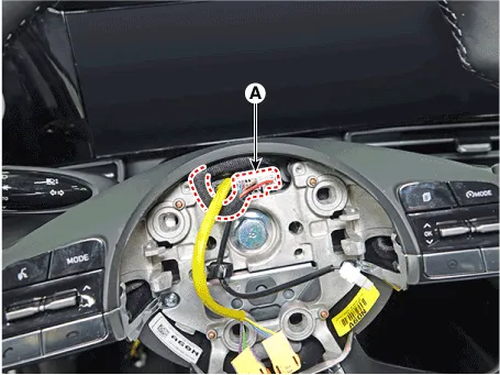
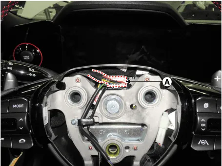
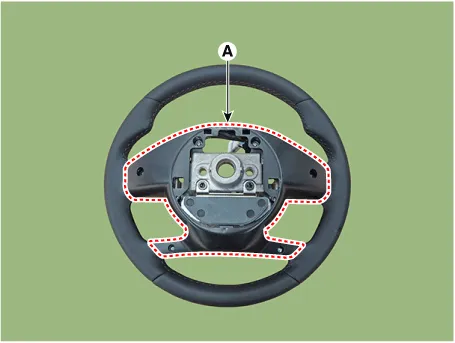
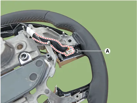
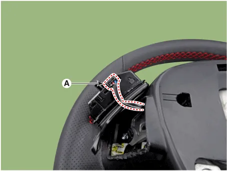
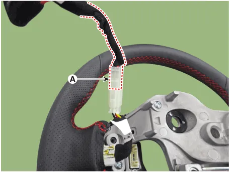
| 4. | Disconnect the steering wheel connector (A). [G 1.6 MPI / LPI]
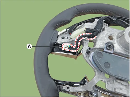
[G 1.6 T-GDI]
|
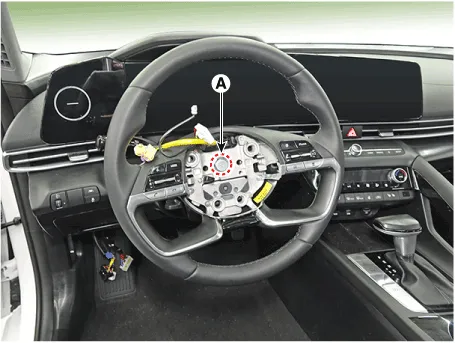
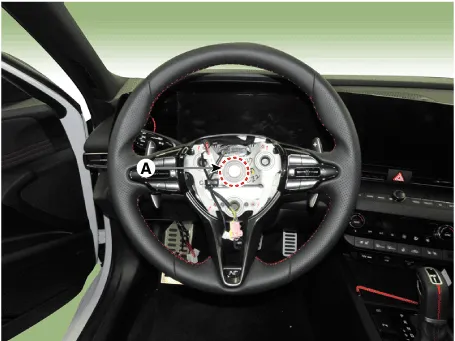
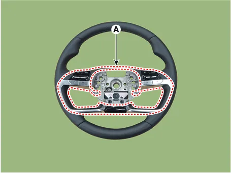
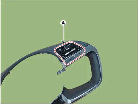
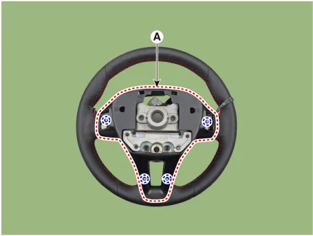
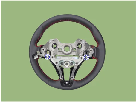
| 5. | Remove the steering wheel after loosening the steering wheel lock bolt (A).
[G 1.6 MPI / LPI]
[G 1.6 T-GDI]
|

| Installation |
| 1. | Install in the reverse order of removal. |
| Disassembly |
| 1. | Remove the lower cover (A) after loosening the screw.
|
| 2. | Disconnect the remote control switch connector (A). [LH]
[RH]
|
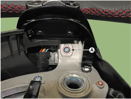
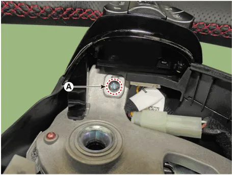
| 3. | Remove the wiring after disconnecting the heated steering wheel connector (A).
|

| 4. | Remove the switch bezel (A) after loosening screw.
|
| 5. | Remove the remote control switch (A) after loosening the screw. [LH]
[RH]
|

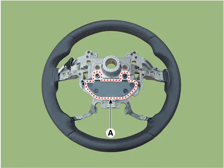
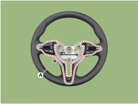
| 6. | Remove the steering wheel damper (A) after loosening the mounting bolts.
|
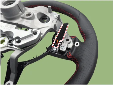
| 1. | Loosen the Paddle shift mounting screw (A). [LH]
[RH]
|
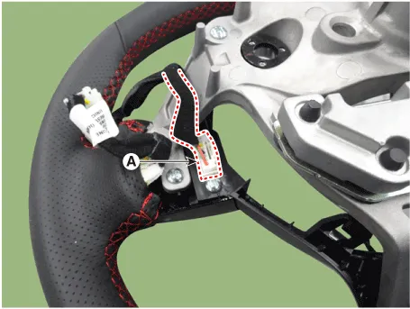
| 2. | Disconnect the Paddle shift connector (A). [LH]
[RH]
|

| 3. | Remove the lower cover (A) after loosening the mounting screw.
|
| 4. | Disconnect the remote control switch connector (A). [LH]
[RH]
|
| 5. | Remove the wiring after disconnecting the heated steering wheel connector (A).
|
| 6. | Remove the switch bezel & remote control switch (A) after loosening the mounting screw.
|
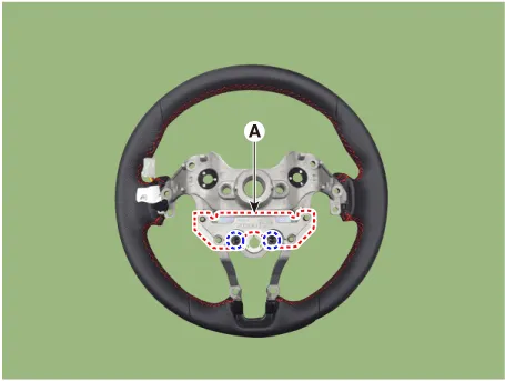
| 7. | Remove the steering wheel damper (A) after loosening the mounting bolts.
|
| Reassembly |
| 1. | To reassembly, reverse the disassembly procedure. |
Components[G 1.6 MPI / LPI]1. Drive air bag module (DAB)2. Wiring3. Steering wheel4. Damper5. Remote control switch6. Switch bezel7. Lower cover[G 1.6 T-GDI]1.
Description and operation DescriptionFor the convenience of drivers during the winter, exothermic paint is applied to the surface of the steering wheel to generate heat when it is gripped.
Other information:
Hyundai Elantra (CN7) 2021-2026 Service Manual: Photo Sensor
Description and operation Description 1.The photo sensor is located at the center of the defrost nozzles.2.The photo sensor contains a photovoltaic (sensitive to sunlight) diode. The solar radiation received by its light receiving portion, generates an electromotive force in proportion to the amount of radiation received which is transferred to
Hyundai Elantra (CN7) 2021-2026 Service Manual: Parking Distance Warning (PDW)
Description and operation Description• PDW consists of 8 sensors (front : 4 units, rear : 4 units) that are used to detect obstacles and transmit the result in three separate warning levels, the first, second and third to IBU via LIN communication.
Categories
- Manuals Home
- Hyundai Elantra Owners Manual
- Hyundai Elantra Service Manual
- Drive Mode
- Troubleshooting
- Brake System
- New on site
- Most important about car
