Hyundai Elantra (CN7): Air Conditioning System / Photo Sensor
Description and operation
| Description |
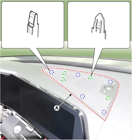
| 1. | The photo sensor is located at the center of the defrost nozzles. |
| 2. | The photo sensor contains a photovoltaic (sensitive to sunlight) diode. The solar radiation received by its light receiving portion, generates an electromotive force in proportion to the amount of radiation received which is transferred to the automatic temperature control module so that the solar radiation compensation will be performed. |
Repair procedures
| Inspection |
| 1. | Emit intensive light toward the photo sensor using a lamp, and check the output voltage change. |
| 2. | The voltage will rise with higher intensive light and reduce with lower intensive light.
|
| Replacement |
| 1. | Disconnect the negative (-) battery terminal. |
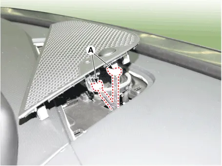
| 2. | Remove the photo sensor cover (A).
|
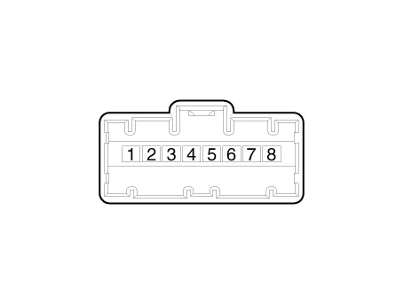
| 3. | Press the lock pin, separate the connectors (A).
|
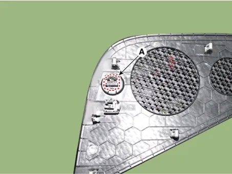
| 4. | Remove the photo sensor (A).
|
| 5. | Install in the reverse order of removal. |
Description and operation DescriptionThe In-car air temperature sensor is built in the heater & A/C control unit.The sensor contains a thermistor which measures the temperature of the inside.
Description and operation DescriptionThe ambient temperature sensor is located at the front of the condenser and detects ambient air temperature. It is a negative type thermistor; resistance will increase with lower temperature, and decrease with higher temperature.
Other information:
Hyundai Elantra (CN7) 2021-2026 Service Manual: Blower Resistor (Manual)
Repair procedures Inspection1.Measure the resistance between the terminals.2.The measured resistance is not within specification, the blower resistor must be replaced. (After removing the resistor)Replacement1.Disconnect the negative (-) battery terminal.
Hyundai Elantra (CN7) 2021-2026 Service Manual: Components and components location
C
Categories
- Manuals Home
- Hyundai Elantra Owners Manual
- Hyundai Elantra Service Manual
- Maintenance
- Drive Mode
- Front Radar Unit
- New on site
- Most important about car

Copyright © 2026 www.helantra7.com - 0.0128