Hyundai Elantra (CN7): Manual Transaxle Control System / Shift Lever
Components and components location
| Components |
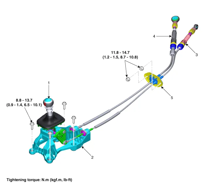
| 1. Shift lever knob & boots 2. Shift lever assembly 3. Select cable | 4. Shift cable 5. Retainer |
Repair procedures
| Removal |
| 1. | Turn OFF ignition switch and disconnect the negative (-) battery cable. |
| 2. | Remove the floor console assembly. (Refer to Body - "Floor Console") |
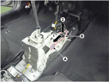
| 3. | Remove the snap pin (A) and then separate the select cable socket (B).
|
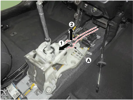
| 4. | Separate the cable socket (A) from the shift lever.
|
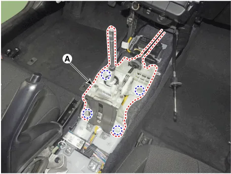
| 5. | Loosen the bolts and then disconnect the shift lever (A).
|
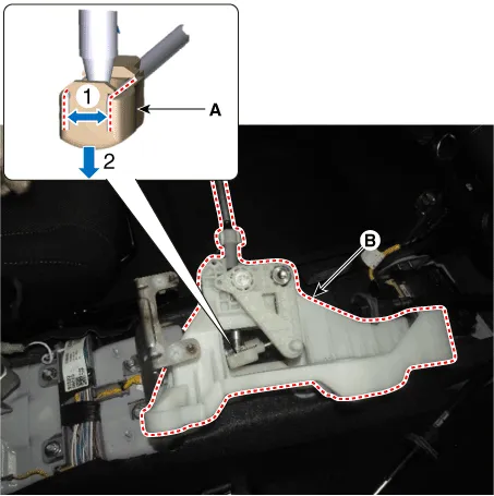
| 6. | Remove the shift cable end (A) and shift lever (B) by spreading the clips on both sides of the cable end.
|
| Installation |
| 1. | To install, reverse the removal procedures. |
|

Components and components location Components1. Shift lever knob & boots2. Shift lever assembly3. Select cable4. Shift cable5. Retainer Repair procedures Removal1.
Other information:
Hyundai Elantra (CN7) 2021-2026 Service Manual: Description and operation
Description and operation The System may be limited when • The radar sensor or camera is blocked with a foreign object or debris.• The camera lens is contaminated due to tinted filmed or coated windshield, damaged glass, or stuck of foreign matter (sticker, bug, etc.
Hyundai Elantra (CN7) 2021-2026 Service Manual: Components and components location
C
Categories
- Manuals Home
- Hyundai Elantra Owners Manual
- Hyundai Elantra Service Manual
- Maintenance
- Rear Seats
- Body Electrical System
- New on site
- Most important about car

Copyright © 2026 www.helantra7.com - 0.0125