Hyundai Elantra (CN7): Manual Transaxle Control System / Control Cable
Components and components location
| Components |
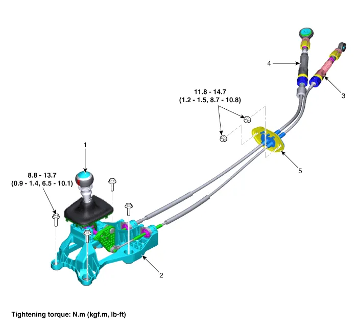
| 1. Shift lever knob & boots 2. Shift lever assembly 3. Select cable | 4. Shift cable 5. Retainer |
Repair procedures
| Removal |
| 1. | Remove the air cleaner assembly and air duct. (Refer to Engine Mechnical System - "Air Cleaner") |
| 2. | Remove the battery and battery tray. (Refer to Engine Electrical System - "Battery") |
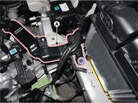
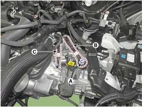
| 3. | Loosen the bolt and then separate the engine wiring (A).
|
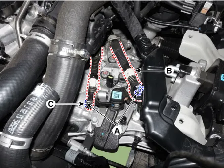
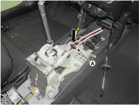
| 4. | Remove the snap pin (A) and then separate the shift cable (B) and the select cable (C) from the control shaft complete.
|
| 5. | Remove the floor console assembly. (Refer to Body - "Floor Console") |
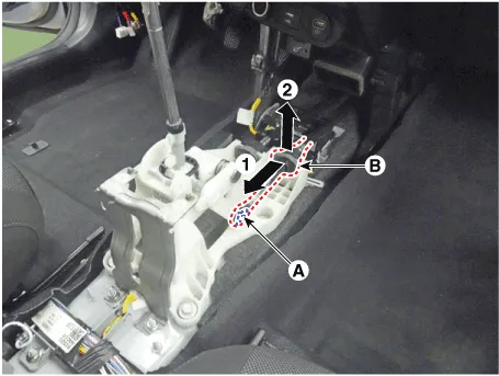
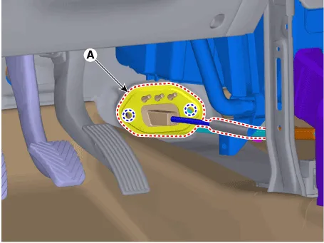
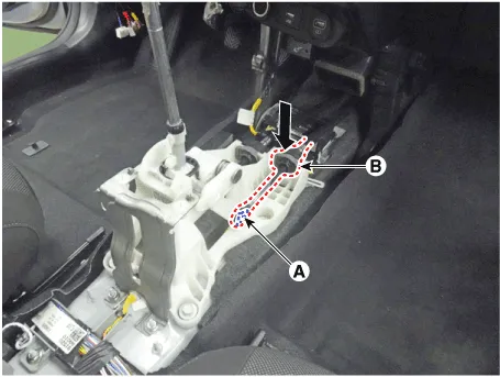
| 6. | Remove the snap pin (A) and then separate the select cable socket (B).
|
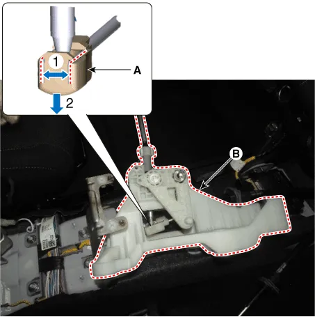
| 7. | Separate the cable socket (A) from the shift lever.
|
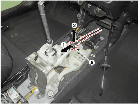
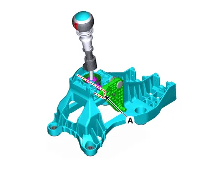
| 8. | Loosen the bolts and then separate the shift lever (A).
|
| 9. | Remove the shift cable end (A) and shift lever (B) by spreading the clips on both sides of the cable end.
|
| 10. | Loosen the nuts and then removing the retainer (B).
|
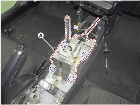
| 11. | Remove the control cable assembly (A) from the vehicle.
|

| Installation |
|

| 1. | Install the retainer (A) and then tighten the nuts.
|
| 2. | Install the shift cable end (A) on the shift lever (B).
|

| 3. | Install the shift lever (A).
|
| 4. | Install the shift cable socket (A).
|
| 5. | Install the select cable (B) and the snap pin (A).
|
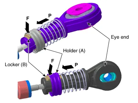
| 6. | Move the locker (B) in the direction of "F" with pulling the holder (A) in the direction of "P".
|

| 7. | Install the shift cable (B) and the select cable (C) and then insert the snap pin (A).
|
| 8. | Tighten the holder (A) to the "P" directions after fixing the rockers (B) in the "F" direction.
|
| 9. | Install the battery and battery tray. (Refer to Engine Electrical System - "Battery") |
| 10. | Install the air cleaner assembly and air duct. (Refer to Engine Mechnical System - "Air Cleaner") |
| 11. | Remove the 4th fixing pin (A).
|
| 12. | Install the floor console assembly. (Refer to Body - "Floor Console") |
|
Components and components location Components1. Shift lever knob & boots2. Shift lever assembly3. Select cable4. Shift cable5. Retainer Repair procedures Removal1.
Description and operation DescriptionComponent location Operation principle : Control shaft assembly is operated by shifting the shift lever.
Other information:
Hyundai Elantra (CN7) 2021-2026 Service Manual: Compressor oil
Repair procedures Oil Specification1.The HFC-134a system requires synthetic (PAG) compressor oil whereas the R-12 system requires mineral compressor oil. The two oils must never be mixed.2.Compressor (PAG) oil varies according to compressor model. Be sure to use oil specified for the model of compressor.
Hyundai Elantra (CN7) 2021-2026 Service Manual: Rear Corner Radar Unit
Specifications Specifications Items Blind-Spot Collision Warning (BCW) Blind-Spot Collision- Avoidance Assist-Rear (BCA-R) Rated voltageDC 12VOperating voltage9V - 16VOperating speed30 km/h - 255 km/h60 km/h - 180 km/hSensible distance70m Curvature radiusStart : More
Categories
- Manuals Home
- Hyundai Elantra Owners Manual
- Hyundai Elantra Service Manual
- Auto Hold. Warning messages
- Instrument Panel Overview
- Repair procedures
- New on site
- Most important about car
