Hyundai Elantra (CN7): Dual Clutch Transmission Control System / Shift Lever
Components and components location
| Components |
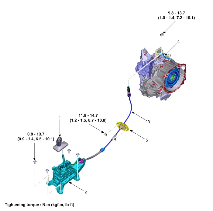
| 1. Shift lever knob & boots assembly 2. Shift lever assembly 3. Shift cable | 4. Manual control lever 5. Shift cable retainer |
Repair procedures
| Removal |
| 1. | Turn OFF ignition switch and then diconnect the battery negative (-) cable. |
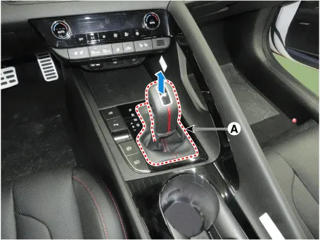
| 2. | Remove the shift lever knob & boots (A).
|
| 3. | Remove the floor console assembly. (Refer to Body - "Floor Console") |
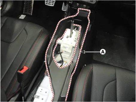
| 4. | Remove the air duct (A) after loosening the bolts.
|
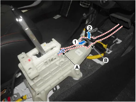
| 5. | Separate the shift cable (B) after removing the snap pin (A).
|
| 6. | Disconnect the connector (A) and wiring clip (B).
|
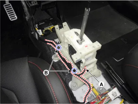
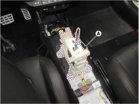
| 7. | Remove the shift lever (A) after loosening the mounting bolts.
|
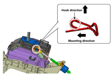
| Installation |
| 1. | To install, reverse the removal procedure.
|


Description and operation Description• The inhibitor switch is installed on top of transmission, and is connected to the shift lever through shift cable.
Components and components location Components1. Shift lever knob & boots assembly2. Shift lever assembly3. Shift cable4. Manual control lever5. Shift cable retainer Repair procedures Removal1.
Other information:
Hyundai Elantra (CN7) 2021-2026 Service Manual: General safety information and caution
General Safety Information and Caution1.Be careful when driving the vehicle using the smart cruise control system as follows.(1)On curves or inclines/declines• The smart cruise control system may have limits to detect distance to the vehicle ahead due to road and traffic conditions.
Hyundai Elantra (CN7) 2021-2026 Service Manual: Troubleshooting
Trouble Symptom ChartsTrouble Symptom 1Trouble Symptom 2 Trouble symptom Probable cause Remedy The set vehicle speed varies greatly upward or downward"Surging" (repeated alternating acceleration and deceleration) occurs after settingMalfunction of the vehicle speed se
Categories
- Manuals Home
- Hyundai Elantra Owners Manual
- Hyundai Elantra Service Manual
- Driver assistance system
- Repair procedures
- Maintenance
- New on site
- Most important about car
