Hyundai Elantra (CN7): Dual Clutch Transmission Control System / Shift Cable
Components and components location
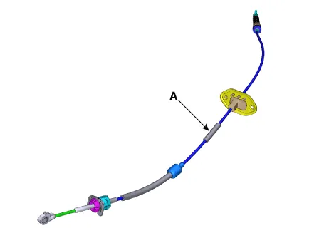
| Components |

| 1. Shift lever knob & boots assembly 2. Shift lever assembly 3. Shift cable | 4. Manual control lever 5. Shift cable retainer |
Repair procedures
| Removal |
| 1. | Remove the air cleaner assembly and air duct. (Refer to Engine Mechnical System - "Air cleaner") |
| 2. | Remove the battery and tray. (Refer to Engine Electrical System - "Battery") |
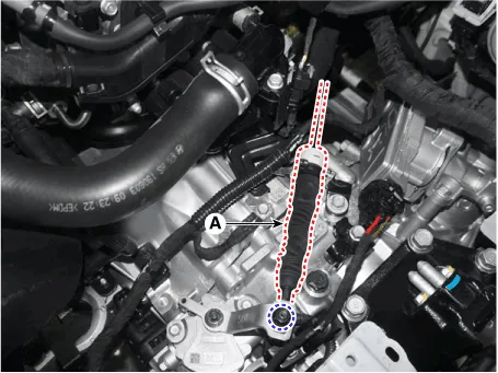
| 3. | Remove the shift cable (A) from the cable bracket, after loosening the mounting nut.
|
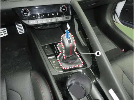
| 4. | Remove the shift lever knob & boots (A).
|
| 5. | Remove the floor console assembly. (Refer to Body - "Floor Console") |
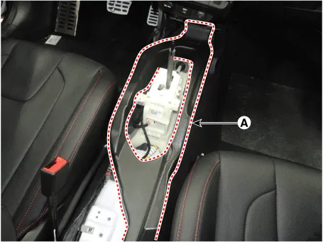
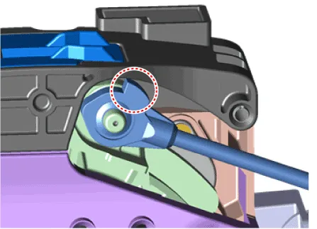
| 6. | Remove the air duct (A) after loosening the bolts.
|
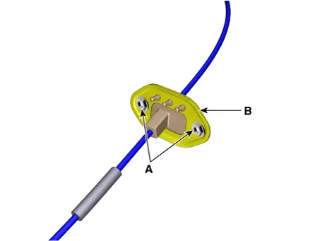
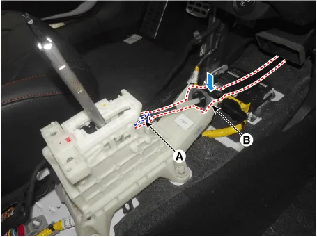
| 7. | Separate the shift cable sorket (B) after removing the snap pin (A).
|

| 8. | Remove the retainer (B) by loosening the nuts (A).
|
| 9. | Remove the shift cable (A) from the vehicle.
|
| Installation |
| 1. | Install the retainer (B) and then tighten the nut (A).
|
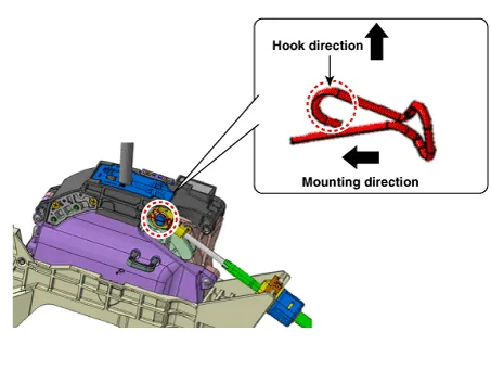
| 2. | Install the shift cable sorket (B) and then fix the snap pin (A).
|

| 3. | Install the air duct (A).
|
| 4. | Install the floor console assembly. (Refer to Body - "Floor Console") |
| 5. | Install the shift lever knob & boots (A).
|

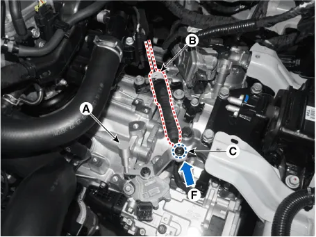
| 6. | Align the hole in the manual control lever with the "N" position hole of the inhibitor switch and then insert the inhibitor switch guide pin (SST No. : 09480 - A3800) (A) in the matched hole. |
| 7. | Push shift cable (B) lightly to "F" direction shown to eliminate free play of shift cable. |
| 8. | Tighten the nut (C) with the specified torque.
|
| 9. | Remove the inhibitor switch guide pin (SST No.:09480-A3800) from the hole. |
| 10. | Install the battery and tray. (Refer to Engine Electrical System - "Battery") |
| 11. | Install the air cleaner assembly and air duct. (Refer to Engine Mechnical System - "Air cleaner")
|
Components and components location Components1. Shift lever knob & boots assembly2. Shift lever assembly3. Shift cable4. Manual control lever5. Shift cable retainer Repair procedures Removal1.
Other information:
Hyundai Elantra (CN7) 2021-2026 Service Manual: Troubleshooting
Trouble Symptom ChartsTrouble Symptom 1Trouble Symptom 2 Trouble symptom Probable cause Remedy The set vehicle speed varies greatly upward or downward"Surging" (repeated alternating acceleration and deceleration) occurs after settingMalfunction of the vehicle speed se
Hyundai Elantra (CN7) 2021-2026 Service Manual: Troubleshooting
Diagnosis with Diagnostic tool1.In the body electrical system, failure can be quickly diagnosed by using the vehicle diagnostic system (Diagnostic tool).The diagnostic system (Diagnostic tool) provides the following information.(1)Fault Code Searching : Checking failure and code number (DTC)(2)Data Analysis : Checking the system input/output data s
Categories
- Manuals Home
- Hyundai Elantra Owners Manual
- Hyundai Elantra Service Manual
- Engine Control / Fuel System
- Driver assistance system
- Auto Hold. Warning messages
- New on site
- Most important about car
