Hyundai Elantra (CN7): Timing System / Timing Chain
Components and components location
| Components |
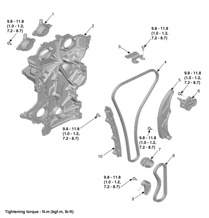
| 1. Variable force solenoid valves 2. Timing chain cover 3. Cam to cam guide 4. Timing chain 5. Timing chain tensioner arm | 6. Timing chain tensioner 7. Crankshaft sprocket 8. Oil pump chain 9. Oil pump chain tensioner 10. Timing chain guide |
Repair procedures
| Removal |
| 1. | Disconnect the battery negative terminal. |
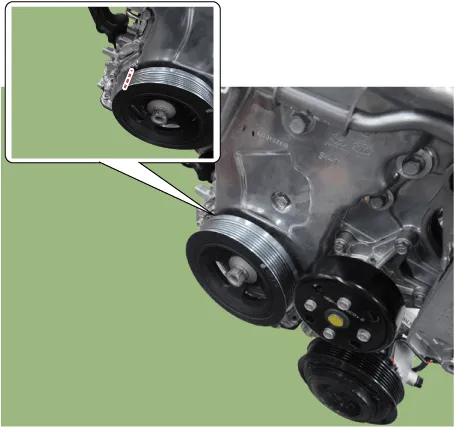
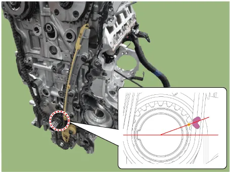
| 2. | Turn the crankshaft damper pulley clockwise, and align its groove with the timing mark of the timing chain cover.
|
| 3. | Remove the timing chain cover. (Refer to Timing System - "Timing Chain Cover") |
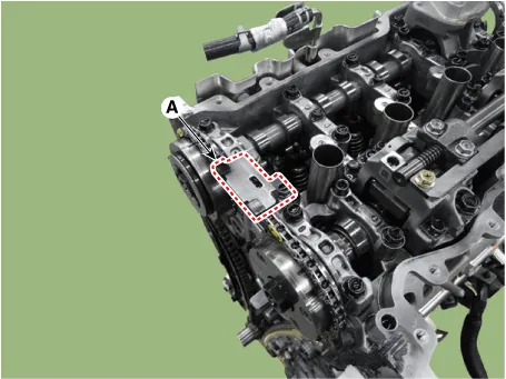
| 4. | Remove the cam to cam guide (A).
|
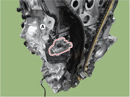
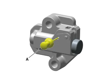
| 5. | Remove the timing chain tensioner (A).
|

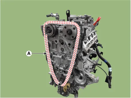
| 6. | Remove the timing chain tensioner arm (A).
|
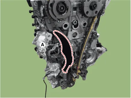
| 7. | Remove the timing chain (A).
|
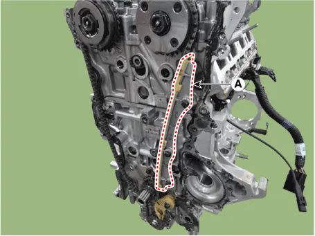
| 8. | Remove the timing chain guide (A).
|
| 9. | Remove the oil pump chain. (Refer to Lubrication System - "Oil Pump") |
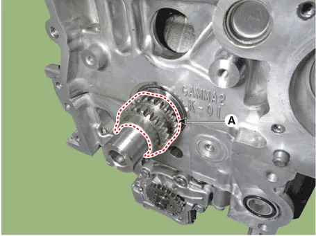
| 10. | Remove the crankshaft sprocket (A).
|
| Inspection |
| 1. | Check the camshaft sprocket, crankshaft sprocket teeth for abnormal wear, cracks or damage. Replace if necessary. |
| 2. | Check a contact surface of the chain tensioner arm and guide for abnormal wear, cracks or damage. Replace if necessary. |
| 3. | Check the hydraulic tensioner for its piston stroke and ratchet operation. Replace if necessary. |
| Installation |
| 1. | Install the crankshaft sprocket (A).
|
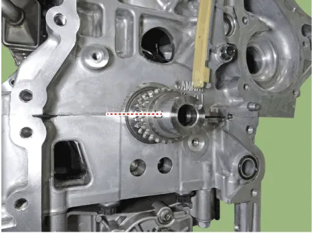
| 2. | Place the crankshaft key at the left 180°.
|
| 3. | Install the oil pump chain. (Refer to Lubrication System - "Oil Pump") |
| 4. | Install the timing chain (A).
|
| 5. | Install the timing chain guide (A).
|
| 6. | Install the timing chain tensioner arm (A).
|
| 7. | Install the timing chain tensioner (A).
|
| 8. | Install the cam to cam guide (A).
|
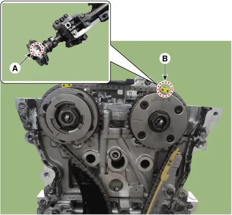
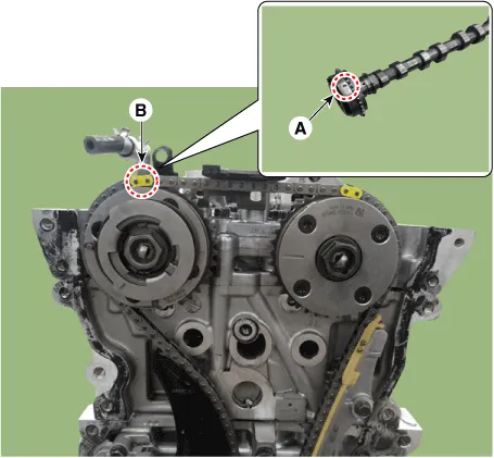
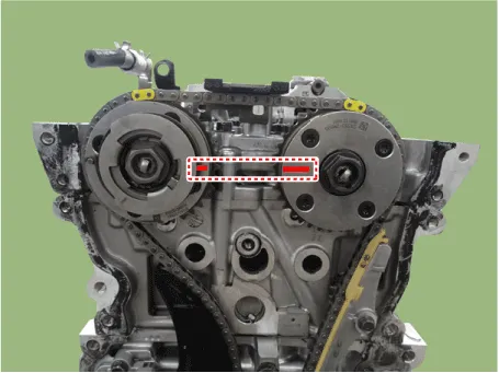
| 9. | After rotating crankshaft 2 revolutions in regular direction (clockwise viewed from front), confirm that the TDC marks on the intake and exhaust CVVT sprockets are aligned with the top surface of cylinder head.
|
| 10. | Install the timing chain cover. (Refer to Timing System - "Timing Chain Cover") |
| 11. | Install the other parts in the reverse order of removal. |
Repair procedures Removal • Use fender covers to avoid damaging painted surfaces. • To avoid damage, unplug the wiring connectors carefully while holding the connector portion.
Other information:
Hyundai Elantra (CN7) 2021-2026 Service Manual: Auto Lighting Control System
Description and operation DescriptionIt's a system that uses illumination sensor to automatically turn ON the tail lamp and head lamp based on the change in surrounding environment's illumination condition. It activates when the vehicle enters/exits tunnel, or when the illumination condition in surrounding environment changes due to rain, snow, or
Hyundai Elantra (CN7) 2021-2026 Service Manual: Parking Collision-Avoidance Assist (PCA)
Components and components location Components and Components Location Schematic diagrams Schematic DiagramsParking Collision-Avoidance Assist (PCA) Ultrasonic sensorParking Collision-Avoidance Assist (PCA) Rear view camera Repair procedures RemovalParking Collision-Avoidance Assist (PCA) Unit1.
Categories
- Manuals Home
- Hyundai Elantra Owners Manual
- Hyundai Elantra Service Manual
- Brake System
- Repair procedures
- Body (Interior and Exterior)
- New on site
- Most important about car
