
Hyundai Elantra (CN7): Tire Pressure Monitoring System / TPMS Receiver
Description and operation
| Description |
TPMS Receiver : BCM(body control module) integrated management

| 1. | Early state
|
| 2. | Normal State
|
| Operation |
| 1. | General Function
|
| 2. | General Conditions to Learn New Sensors
|
| 3. | General Conditions to Un-Learn a sensor that is removed
|
Repair procedures
| Replacement |
[TPMS Receiver (Integrated Body Unit (IBU))]
| 1. | Turn the ignition switch OFF and disconnect the battery negative (-) cable. |
| 2. | Remove the glove box. (Refer to Body - "Glove Box") |
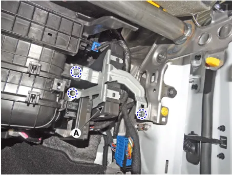
| 3. | Remove the IBU (A) after loosening the mounting nuts and bolt.
|
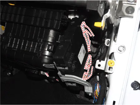
| 4. | Remove the IBU after disconnecting the connector.
|
| 5. | To install, reverse the removal procedures. |
| 6. | learn by connecting diagnostic tool. |
| 7. | Perform TPMS test to check for any abnormality. |
| Diagnosis procedure by using diagnostic device |
The main contents of diagnostic method using diagnostic device are as follows:
| 1. | Connect self-diagnosis connector (16 pins) located in the lower driver side crash pad to self-diagnosis device, and then turn on the self-diagnosis device after key is ON. |
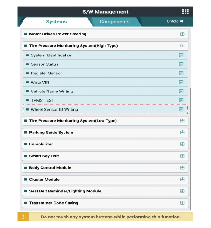
| 2. | Select the "vehicle model" and "TPMS" on GDS vehicle selection screen, then select OK. |
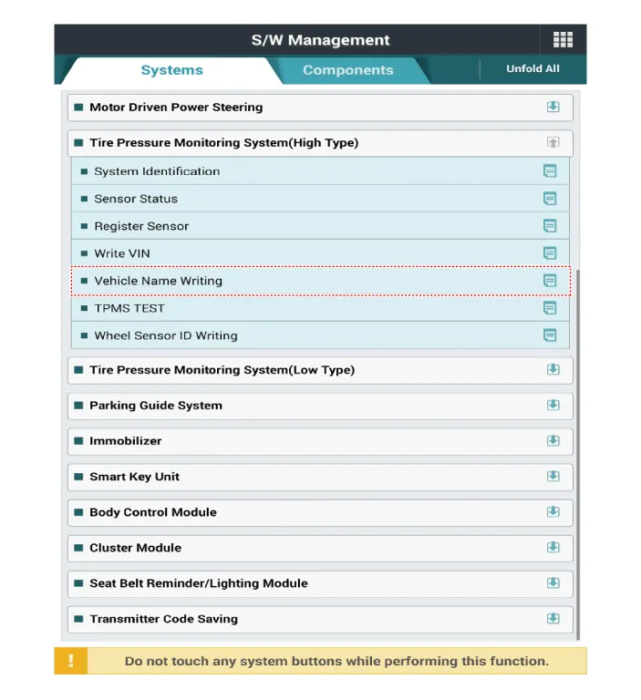
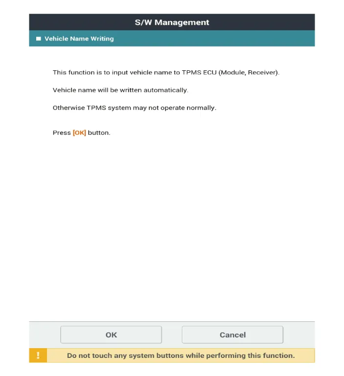
[Vehicle Name Writing Method]



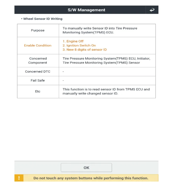
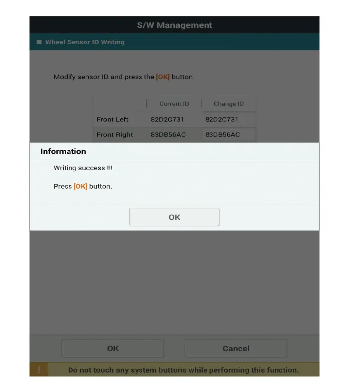
[Wheel Sensor ID Writing Method]


| Inspection |
| 1. | Check the vehicle code, VIN, sensor ID storage and normal storage in the receiver. |
| 2. | Check if the TPMS receiver [Integrated Body Unit (IBU)] status is normal. |
| 3. | Check whether the TPMS warning light is off and DTC. |
Description and operation Description 1.Function• By detecting the pressure, temperature, acceleration, and battery condition, transmit information to ECU by a wireless RF.
Other information:
Hyundai Elantra (CN7) 2021-2026 Service Manual: Blower Unit
Components and components location Component Location1. Blower unit assemblyComponents1. Blower unit assebmly2. Blower upper cover [LH]3. Duct seal4. Blower upper cover [RH]5. Intake actuator6. Air filter cover7. Intake door8. Air filter9. Blower upper case10.
Hyundai Elantra (CN7) 2021-2026 Service Manual: Components and components location
C
Categories
- Manuals Home
- Hyundai Elantra Owners Manual
- Hyundai Elantra Service Manual
- Body Electrical System
- Body (Interior and Exterior)
- General Tightening Torque Table. General information
- New on site
- Most important about car

Copyright © 2026 www.helantra7.com - 0.0131