Hyundai Elantra: Dual Clutch System / Dual Clutch Assembly
Hyundai Elantra (CN7) 2021-2025 Service Manual / DCT(Dual Clutch Transmission) System / Dual Clutch System / Dual Clutch Assembly
Components and components location
| Components |
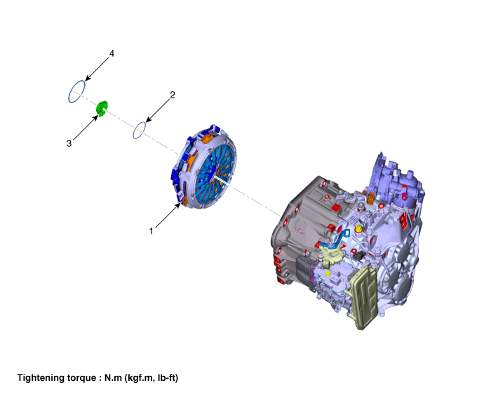
| 1. Dual clutch assembly 2. Snap ring | 3. Spline hub 4. Retaining ring |
Repair procedures
| Removal |
| 1. | Remove the dual clutch transmission from the vehicle. (Refer to Dual Clutch System - "Repair procedures") |
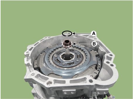
| 2. | Remove the retaining (A) and then removing the spline hub (B).
|
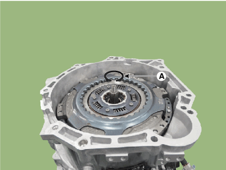
| 3. | Remove the snap ring (A).
|
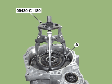
| 4. | Remove the dual clutch assembly (A) by using the special service tool [SST No.: 09430-C1180].
|
| Installation |
|
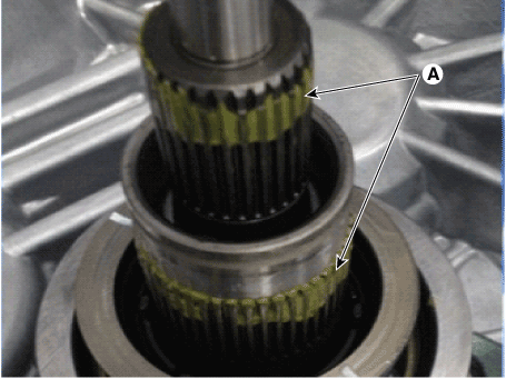
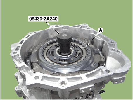
| 1. | Install the SST (No.:09430-2A240) on the support bearing within the dual clutch assembly (A).
|
| 2. | Install the SST (No. : 09430-2A240) on the clutch housing side. |
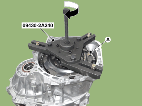
| 3. | Install the dual clutch assembly (A) using the SST (No. : 09430-2A240).
|
| 4. | Install the snap ring (A).
|
| 5. | Install the spline hub (B) and the install the snap ring (A).
|
| 6. | Perform the work procedures for abrasion compensation reset after installing the new dual clutch assembly. (Refer to Clutch Actuator Assembly - "Adjustment") |
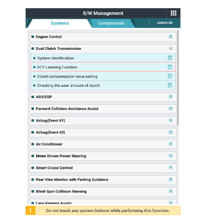
| 7. | Perform the clutch touch point learning procedure using the diagnostic tool after replacing the dual clutch assembly.
|
 Description and operation
Description•
Components location : DCT (Dual Clutch Transmission)•
Function
The dual clutch is installed within the transmission...
 Clutch Engagement Fork and Engagement Bearing
Components and components location
Components1. Engagement bearing sleeve2. Clutch engagement fork3. Engagement bearing 1 (Odd)4. Engagement bearing 2 (Even)5...
Other information:
Hyundai Elantra (CN7) 2021-2025 Owner's Manual: Explanation of Scheduled Maintenance Items
Engine Oil and Filter The engine oil and filter should be changed at the intervals specified in the maintenance schedule. If the vehicle is being driven in severe conditions, more frequent oil and filter changes are required. Drive Belts Inspect all drive belts for evidence of cuts, cracks, excessive wear or oil saturation and replace if necessary...
Hyundai Elantra (CN7) 2021-2025 Service Manual: Components and components location
Components Location1. Front view camera (FR_CMR)2. LKA ON/OFF switch (Remote control switch)3. LKA ON/OFF switch4. Cluster5. AVN head unit..
Copyright © 2025 www.helantra7.com


.png)