Hyundai Elantra (CN7): Emergency Call System / Emergency Call (eCall) Antenna
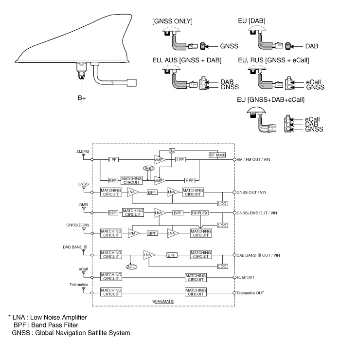
Schematic diagrams
| Components |
Repair procedures
| Removal |
| 1. | Disconnect the negative (-) battery terminal. |
| 2. | Remove the roof trim. (Refer to Body - "Roof Trim Assembly") |
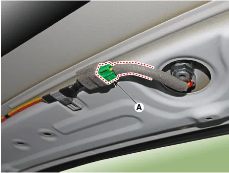
| 3. | Disconnect the roof antenna connector (A).
|
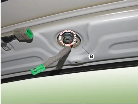
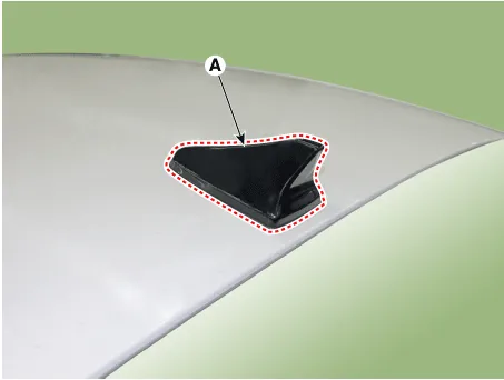
| 4. | Remove the roof antenna (A) after loosening a nut (B).
|
| 1. | Disconnect the negative (-) battery terminal. |
| 2. | Remove the main crash pad assembly. (Refer to Body - "Main Crash Pad Assembly") |
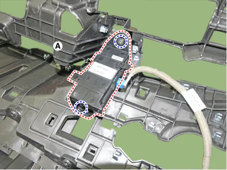
| 3. | Loosen the mounting screws and then remove the crash pad antenna (A).
|
| Installation |
| 1. | Connect the roof antenna connectors. |
| 2. | Install the roof trim assembly.
|

| 1. | Connect the roof antenna connectors and install the roof antenna. |
| 2. | Install the main crash pad assembly. |
Components and components location Component Repair procedures Removal1.Disconnect the negative (-) battery terminal.2.Using a remover and remove the overhead console (A).
Other information:
Hyundai Elantra (CN7) 2021-2026 Service Manual: A/C Pressure Transducer
Description and operation DescriptionThe A/C Pressure Transducer (APT) converts the pressure value of high pressure line into voltage value after measuring it. By converted voltage value, engine ECU controls the cooling fan by operating it high speed or low speed.
Hyundai Elantra (CN7) 2021-2026 Service Manual: Description and operation
Description and operation The System may be limited when • The radar sensor or camera is blocked with a foreign object or debris.• The camera lens is contaminated due to tinted filmed or coated windshield, damaged glass, or stuck of foreign matter (sticker, bug, etc.
Categories
- Manuals Home
- Hyundai Elantra Owners Manual
- Hyundai Elantra Service Manual
- Steering System
- Troubleshooting
- Repair procedures
- New on site
- Most important about car
