Hyundai Elantra (CN7): Engine Control System / Engine Control Module (ECM)
Schematic diagrams
| ECM Terminal And Input/Output signal |
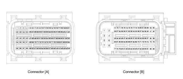
| ECM Terminal Function |
|
Pin No
|
Description
|
| 1 | Fuel Pressure Control Valve (FPCV) [High] control |
| 2 | Integrated Thermal Mangement Module (ITM) Motor (+) |
| 3 | Integrated Thermal Mangement Module (ITM) Motor (-) |
| 4 | - |
| 5 | Engine Coolant Temperature Sensor (ECTS) #1 (Ground) |
| 6 | - |
| 7 | Engine Coolant Temperature Sensor (ECTS) #2 (Ground) |
| 8 | - |
| 9 | Rail Pressure Sensor (RPS) (Ground) |
| 10 | - |
| 11 | Manifold Absolute Pressure Sensor (MAPS) (Ground) |
| 12 | Electric WGT Control Actuator (EWGA) (Ground) |
| 13 | - |
| 14 | Oil Pressure & Temperature Sensors (OPTS) (Ground) |
| 15 | - |
| 16 | - |
| 17 | A/C Pressure Transducer (APT) (Ground) |
| 18 | Sensor Power (+5V) (Camshaft Position Sensor (CMPS) [Bank 1 / Intake, Exhaust]) |
| 19 | Sensor Power (+5V) (MAPS, CKPS) |
| 20 | Sensor Power (+5V) (OPS, ETC, RPS) |
| 21 | Sensor Ground (Throttle Position Sensor (TPS)) |
| 22 | - |
| 23 | - |
| 24 | Sensor Shield (Knock Sensor (KS)) |
| 25 | - |
| 26 | Ignition Coil (Cylider #3) Control |
| 27 | - |
| 28 | - |
| 29 | - |
| 30 | - |
| 31 | - |
| 32 | - |
| 33 | - |
| 34 | - |
| 35 | Integrated Thermal Mangement Module (ITM) Motor (Ground) |
| 36 | - |
| 37 | Camshaft Position Sensor (CMPS) [Bank 1 / Intake] Signal |
| 38 | - |
| 39 | Electric WGT Control Actuator (EWGA) Signal |
| 40 | Sensor Power (+5V) (EWGA) |
| 41 | Sensor Power (+5V) (APS #1) |
| 42 | Sensor Power (+5V) (APT) |
| 43 | Injector (Cylinder #3) [+] Control |
| 44 | Injector (Cylinder #2) [+] Control |
| 45 | - |
| 46 | - |
| 47 | CCP-CAN (High) |
| 48 | Ignition Coil (Cylider #1) Control |
| 49 | - |
| 50 | - |
| 51 | - |
| 52 | - |
| 53 | - |
| 54 | - |
| 55 | - |
| 56 | - |
| 57 | - |
| 58 | - |
| 59 | - |
| 60 | Camshaft Position Sensor (CMPS) [Bank 1 / Exhaust] (Ground) |
| 61 | - |
| 62 | - |
| 63 | Engine RPM Output |
| 64 | Injector (Cylinder #1) [+] Control |
| 65 | Injector (Cylinder #4) [+] Control |
| 66 | Injector (Cylinder #3) [-] Control |
| 67 | Injector (Cylinder #4) [-] Control |
| 68 | Ignition Coil (Cylider #2) Control |
| 69 | CCP-CAN (Low) |
| 70 | Camshaft Position Sensor (CMPS) [Bank 1 / Exhaust] Signal |
| 71 | Crankshaft Position Sensor (CKPS) (Ground) |
| 72 | Ignition Lock Switch Control |
| 73 | Oil Pressure Sensor (OPS) Signal |
| 74 | Intake Air Temperature Sensor (IATS) Signal |
| 75 | Engine Coolant Temperature Sensor (ECTS) #1 Signal |
| 76 | Engine Coolant Temperature Sensor (ECTS) #2 Signal |
| 77 | - |
| 78 | - |
| 79 | Throttle Position Sensor (TPS) 2 Signal |
| 80 | Rail Pressure Sensor (RPS) Signal |
| 81 | - |
| 82 | Integrated Thermal Mangement Module (ITM) Motor Signal |
| 83 | - |
| 84 | A/C Pressure Transducer (APT) Signal |
| 85 | - |
| 86 | Injector (Cylinder #2) [-] Control |
| 87 | Injector (Cylinder #1) [-] Control |
| 88 | Fuel Pressure Control Valve (FPCV) [Low] control |
| 89 | - |
| 90 | Ignition Coil (Cylider #4) Control |
| 91 | Crankshaft Position Sensor (CKPS) Signal |
| 92 | Integrated Body Control Unit (IBU) External Wake-Up Signal |
| 93 | Heated Oxygen Sensor (HO2S) [Bank 1 / Sensor 2] (Ground) |
| 94 | - |
| 95 | Heated Oxygen Sensor (HO2S) [Bank 1 / Sensor 1] Signal |
| 96 | - |
| 97 | Oil Temperature Sensor (OTS) Signal |
| 98 | Throttle Position Sensor (TPS) 1 Signal |
| 99 | - |
| 100 | - |
| 101 | Manifold Absolute Pressure Sensor (MAPS) Signal |
| 102 | Camshaft Position Sensor (CMPS) [Bank 1 / Intake] (Ground) |
| 103 | - |
| 104 | Knock Sensor (KS) Signal |
| 105 | Knock Sensor (KS) (Ground) |
|
Pin No
|
Description
|
| 1 | Chassis Ground |
| 2 | Chassis Ground |
| 3 | Battery power (B+) (Battery) |
| 4 | Chassis Ground |
| 5 | Battery power (B+) (Main Relay) |
| 6 | Battery power (B+) (Main Relay) |
| 7 | - |
| 8 | - |
| 9 | Sensor Power (+5V) (ITM Motor) |
| 10 | Sensor Power (+5V) (APS #2) |
| 11 | Boost Pressure Sensor (BPS) Signal Input |
| 12 | Accelerator Position Sensor (APS #2) (Ground) |
| 13 | Accelerator Position Sensor (APS #1) (Ground) |
| 14 | - |
| 15 | - |
| 16 | Boost Pressure Sensor (BPS) (Ground) |
| 17 | Fuel Level Sender (FLS) Signal |
| 18 | Accelerator Position Sensor (APS #2) Signal |
| 19 | - |
| 20 | - |
| 21 | - |
| 22 | Rail Pressure Sensor (RPS) Control |
| 23 | Cooling Fan Relay [PMW] Control |
| 24 | EWGA DC Motor Control (+) |
| 25 | EWGA DC Motor Control (-) |
| 26 | Ignition Switch Signal Input |
| 27 | Sensor Power (+5V) (BPS) |
| 28 | - |
| 29 | - |
| 30 | Brake [Test] Switch Signal Input |
| 31 | Brake [Light] Switch Signal Input |
| 32 | Accelerator Position Sensor (APS #1) Signal |
| 33 | - |
| 34 | - |
| 35 | Engine Start Switch Signal Input |
| 36 | - |
| 37 | Fuel Pump Relay Control [Without Smart Key] Control |
| 38 | - |
| 39 | - |
| 40 | Variable Oil Pump Valve Control |
| 41 | ETC Motor [+] Control |
| 42 | ETC Motor [-] Control |
| 43 | - |
| 44 | - |
| 45 | P-CAN (Low) |
| 46 | - |
| 47 | - |
| 48 | Clutch Switch Control |
| 49 | Wiper Switch Input |
| 50 | - |
| 51 | Start Relay (Low) Control |
| 52 | - |
| 53 | - |
| 54 | Electric load Signal Input [Defrost] |
| 55 | - |
| 56 | - |
| 57 | - |
| 58 | - |
| 59 | - |
| 60 | Battery power (B+) (Battery) |
| 61 | LIN Communication Signal Input |
| 62 | P-CAN (High) |
| 63 | - |
| 64 | Heated Oxygen Sensor (HO2S) [Bank 1 / Sensor 1] VS-/IP- (Virtual Ground) |
| 65 | Heated Oxygen Sensor (HO2S) [Bank 1 / Sensor 1] Rc/Rp (Pumping Cell Current) |
| 66 | Heated Oxygen Sensor (HO2S) [Bank 1 / Sensor 1] Rc (Adjust Resistance) |
| 67 | Heated Oxygen Sensor (HO2S) [Bank 1 / Sensor 1] VS+ (NERNST Cell Current) |
| 68 | - |
| 69 | - |
| 70 | - |
| 71 | Start Relay (High) Control |
| 72 | - |
| 73 | - |
| 74 | Engine Control Relay Control |
| 75 | Heated Oxygen Sensor (HO2S) [Bank 1 / Sensor 1] Heater Control |
| 76 | Heated Oxygen Sensor (HO2S) [Bank 1 / Sensor 2] Heater Control |
| 77 | Vehicle Speed Input (IBU, VDC Moduel) |
| 78 | CCP-CAN (High) |
| 79 | CCP-CAN (Low) |
| 80 | - |
| 81 | - |
| 82 | - |
| 83 | Purge Control Solenoid Valve (PCSV) Control |
| 84 | Fuel Pump Relay Control [With Smart Key] Control |
| 85 | - |
| 86 | - |
| 87 | Integrated Body Control Unit (IBU) (IMMO, Data Line) |
| 88 | - |
| 89 | - |
| 90 | - |
| 91 | - |
| 92 | Variable Force Solenoid (VFS) [Bank 1 / Intake] Control |
| 93 | Variable Force Solenoid (VFS) [Bank 1 / Exhaust] Control |
Repair procedures
| Removal |
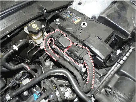
| 1. | Turn ignition switch OFF and disconnect the battery negative (-) terminal. |
| 2. | Disconnect the ECM Connector (A).
|
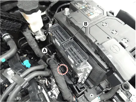
| 3. | Remove the ECM (B) after releasing the fixing hooks (A).
|
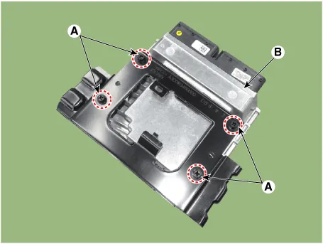
| 4. | Remove the ECM (B) after loosening the mounting bolts (A).
|
| Installation |
| 1. | Install in the reverse order of removal. |
| Inspection |
| 1. | TEST ECM GROUND CIRCUIT : Measure resistance between ECM and chassis ground using the backside of ECM harness connector as ECM side check point. If the problem is found, repair it.
|
| 2. | TEST ECM CONNECTOR : Disconnect the ECM connector and visually check the ground terminals on ECM side and harness side for bent pins or poor contact pressure. If the problem is found, repair it. |
| 3. | If problem is not found in Step 1 and 2, the ECM could be faulty. If so, make sure there were no DTC's before swapping the ECM with a new one, and then check the vehicle again. If DTC's were found, examine this first before swapping ECM. |
| 4. | RE-TEST THE ORIGINAL ECM : Install the original ECM (may be broken) into a known-good vehicle and check the vehicle. If the problem occurs again, replace the original ECM with a new one. If problem does not occur, this is intermittent problem. (Refer to "Intermittent Problem Inspection Procedure" in Basic Inspection Procedure) |
| Adjustment |
[In the case of installing used ECM]
[In the case of installing new ECM]
|

[In the case of installing used ECM]
[In the case of installing new ECM]
|
|
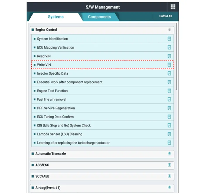
| 1. | Turn the ignition switch OFF. |
| 2. | Connect the diagnostic tool to Data Link Connector (DLC). |
| 3. | Turn the igntion switch ON. |
| 4. | Select "Vehicle, Model Year, Engine, System". |
| 5. | Select "Vehicle S/W Management". |
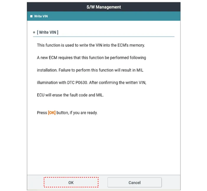
| 6. | Select "Write VIN".
|
Components Location1. Engine Control Module (ECM)2. Manifold Absolute Pressure Sensor (MAPS)3. Intake Air Temperature Sensor (IATS)4. Boost Pressure Sensor (BPS)5.
Description and operation DescriptionBoost pressure sensor (BPS) is installed on top of intercooler output pipe to measures the pressure of supercharged air in the turbocharger.
Other information:
Hyundai Elantra (CN7) 2021-2026 Service Manual: Repair procedures
Refrigerant System Service Basics (R-134a)Refrigerant Recovery Use only service equipment that is U.L-listed and is certified to meet the requirements of SAE J2210 to remove HFC-134a(R-134a) from the air conditioning system. • Air conditioning refrigerant or lubricant vapor can irritate your eyes, nose, or
Hyundai Elantra (CN7) 2021-2026 Service Manual: Mode Control Actuator
Description and operation DescriptionThe mode control actuator is located at the heater unit.It adjusts the position of the mode door by operating the mode control actuator based on the signal of the A/C control unit. Pressing the mode select switch makes the mode control actuator shift in order of Vent → Bi-Level → Floor → Mix.
Categories
- Manuals Home
- Hyundai Elantra Owners Manual
- Hyundai Elantra Service Manual
- Recommended Lubricants and Capacities
- General Tightening Torque Table. General information
- Engine Control / Fuel System
- New on site
- Most important about car
