Hyundai Elantra (CN7): Engine Control System / Boost Pressure Sensor (BPS)
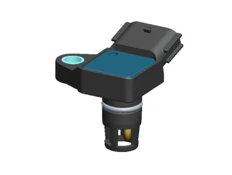
Description and operation
| Description |
Specifications
| Specification |
|
Pressure
[kPa (kgf/cm², psi)] |
Output Voltage (V)
[Vref = 5.0V] |
| 10 (0.10, 1.45) | 0.5 |
| 40 (0.40, 5.80) | 0.91 |
| 80 (0.81, 11.60) | 1.47 |
| 120 (1.22, 17.40) | 2.02 |
| 160 (1.63, 23.20) | 2.57 |
| 200 (2.03, 29.00) | 3.12 |
| 220 (2.24, 31.90) | 3.4 |
| 240 (2.44, 34.80) | 3.67 |
| 280 (2.85, 40.61) | 4.22 |
| 300 (3.05 43.51) | 4.5 |
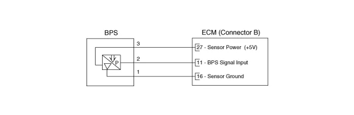
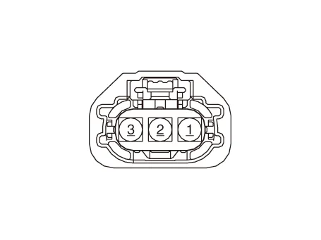
Schematic diagrams
| Circuit Diagram |
Repair procedures
| Inspection |
| 1. | Connect the diagnostic tool on the Data Link Connector (DLC). |
| 2. | Measure the BPS output voltage in IG ON and idle.
|
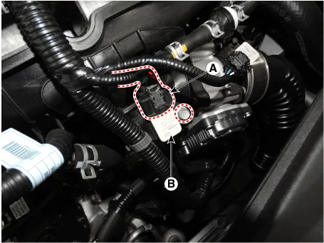
| Removal |
| 1. | Turn ignition switch OFF and disconnect the battery negative (-) terminal. |
| 2. | Disconnect the boost pressure sensor connector (A). |
| 3. | Remove the sensor (B) after remove the mounting bolt.
|
| Installation |
|

| 1. | Install in the reverse order of removal. |
Schematic diagrams ECM Terminal And Input/Output signalECM Terminal FunctionConnector [A] Pin No Description 1Fuel Pressure Control Valve (FPCV) [High] control2Integrated Thermal Mangement Module (ITM) Motor (+)3Integrated Thermal Mangement Module (ITM) Motor (-)4-5Engine Coolant Temperature Sensor (ECTS) #1 (Ground)6-7Engine Coolant Temperature Sensor (ECTS) #2 (Ground)8-9Rail Pressure Sensor (RPS) (Ground)10-11Manifold Absolute Pressure Sensor (MAPS) (Ground)12Electric WGT Control Actuator (EWGA) (Ground)13-14Oil Pressure & Temperature Sensors (OPTS) (Ground)15-16-17A/C Pressure Transducer (APT) (Ground)18Sensor Power (+5V) (Camshaft Position Sensor (CMPS) [Bank 1 / Intake, Exhaust])19Sensor Power (+5V) (MAPS, CKPS)20Sensor Power (+5V) (OPS, ETC, RPS)21Sensor Ground (Throttle Position Sensor (TPS))22-23-24Sensor Shield (Knock Sensor (KS))25-26Ignition Coil (Cylider #3) Control27-28-29-30-31-32-33-34-35Integrated Thermal Mangement Module (ITM) Motor (Ground)36-37Camshaft Position Sensor (CMPS) [Bank 1 / Intake] Signal38-39Electric WGT Control Actuator (EWGA) Signal40Sensor Power (+5V) (EWGA)41Sensor Power (+5V) (APS #1)42Sensor Power (+5V) (APT)43Injector (Cylinder #3) [+] Control44Injector (Cylinder #2) [+] Control45-46-47CCP-CAN (High)48Ignition Coil (Cylider #1) Control49-50-51-52-53-54-55-56-57-58-59-60Camshaft Position Sensor (CMPS) [Bank 1 / Exhaust] (Ground)61-62-63Engine RPM Output64Injector (Cylinder #1) [+] Control65Injector (Cylinder #4) [+] Control66Injector (Cylinder #3) [-] Control67Injector (Cylinder #4) [-] Control68Ignition Coil (Cylider #2) Control69CCP-CAN (Low)70Camshaft Position Sensor (CMPS) [Bank 1 / Exhaust] Signal71Crankshaft Position Sensor (CKPS) (Ground)72Ignition Lock Switch Control73Oil Pressure Sensor (OPS) Signal74Intake Air Temperature Sensor (IATS) Signal75Engine Coolant Temperature Sensor (ECTS) #1 Signal76Engine Coolant Temperature Sensor (ECTS) #2 Signal77-78-79Throttle Position Sensor (TPS) 2 Signal80Rail Pressure Sensor (RPS) Signal81-82Integrated Thermal Mangement Module (ITM) Motor Signal83-84A/C Pressure Transducer (APT) Signal85-86Injector (Cylinder #2) [-] Control87Injector (Cylinder #1) [-] Control88Fuel Pressure Control Valve (FPCV) [Low] control89-90Ignition Coil (Cylider #4) Control91Crankshaft Position Sensor (CKPS) Signal92Integrated Body Control Unit (IBU) External Wake-Up Signal93Heated Oxygen Sensor (HO2S) [Bank 1 / Sensor 2] (Ground)94-95Heated Oxygen Sensor (HO2S) [Bank 1 / Sensor 1] Signal96-97Oil Temperature Sensor (OTS) Signal98Throttle Position Sensor (TPS) 1 Signal99-100-101Manifold Absolute Pressure Sensor (MAPS) Signal102Camshaft Position Sensor (CMPS) [Bank 1 / Intake] (Ground)103-104Knock Sensor (KS) Signal105Knock Sensor (KS) (Ground)Connector [B] Pin No Description 1Chassis Ground2Chassis Ground3Battery power (B+) (Battery)4Chassis Ground5Battery power (B+) (Main Relay)6Battery power (B+) (Main Relay)7-8-9Sensor Power (+5V) (ITM Motor)10Sensor Power (+5V) (APS #2)11Boost Pressure Sensor (BPS) Signal Input12Accelerator Position Sensor (APS #2) (Ground)13Accelerator Position Sensor (APS #1) (Ground)14-15-16Boost Pressure Sensor (BPS) (Ground)17Fuel Level Sender (FLS) Signal18Accelerator Position Sensor (APS #2) Signal19-20-21-22Rail Pressure Sensor (RPS) Control23Cooling Fan Relay [PMW] Control24EWGA DC Motor Control (+)25EWGA DC Motor Control (-)26Ignition Switch Signal Input27Sensor Power (+5V) (BPS)28-29-30Brake [Test] Switch Signal Input31Brake [Light] Switch Signal Input32Accelerator Position Sensor (APS #1) Signal33-34-35Engine Start Switch Signal Input36-37Fuel Pump Relay Control [Without Smart Key] Control38-39-40Variable Oil Pump Valve Control41ETC Motor [+] Control42ETC Motor [-] Control43-44-45P-CAN (Low)46-47-48Clutch Switch Control49Wiper Switch Input50-51Start Relay (Low) Control 52-53-54Electric load Signal Input [Defrost]55-56-57-58-59-60Battery power (B+) (Battery)61LIN Communication Signal Input62P-CAN (High)63-64Heated Oxygen Sensor (HO2S) [Bank 1 / Sensor 1] VS-/IP- (Virtual Ground)65Heated Oxygen Sensor (HO2S) [Bank 1 / Sensor 1] Rc/Rp (Pumping Cell Current)66Heated Oxygen Sensor (HO2S) [Bank 1 / Sensor 1] Rc (Adjust Resistance)67Heated Oxygen Sensor (HO2S) [Bank 1 / Sensor 1] VS+ (NERNST Cell Current)68-69-70-71Start Relay (High) Control72-73-74Engine Control Relay Control75Heated Oxygen Sensor (HO2S) [Bank 1 / Sensor 1] Heater Control76Heated Oxygen Sensor (HO2S) [Bank 1 / Sensor 2] Heater Control77Vehicle Speed Input (IBU, VDC Moduel)78CCP-CAN (High)79CCP-CAN (Low)80-81-82-83Purge Control Solenoid Valve (PCSV) Control84Fuel Pump Relay Control [With Smart Key] Control85-86-87Integrated Body Control Unit (IBU) (IMMO, Data Line)88-89-90-91-92Variable Force Solenoid (VFS) [Bank 1 / Intake] Control93Variable Force Solenoid (VFS) [Bank 1 / Exhaust] Control Repair procedures Removal1.
Description and operation DescriptionThe Electronic Throttle Control (ETC) System consists of a throttle body with an integrated control motor and throttle position sensor (TPS).
Categories
- Manuals Home
- Hyundai Elantra Owners Manual
- Hyundai Elantra Service Manual
- Driver assistance system
- Repair procedures
- Engine Control / Fuel System
- New on site
- Most important about car
