Hyundai Elantra (CN7): Engine Control System / ETC (Electronic Throttle control) System
Description and operation
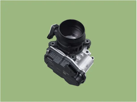
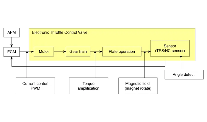
The Electronic Throttle Control (ETC) System consists of a throttle body with an integrated control motor and throttle position sensor (TPS). Instead of the traditional throttle cable, an Accelerator Position Sensor (APS) is used to receive driver input. The ECM uses the APS signal to calculate the target throttle angle; the position of the throttle is then adjusted via ECM control of the ETC motor. The TPS signal is used to provide feedback regarding throttle position to the ECM. Using ETC, precise control over throttle position is possible; the need for external cruise control modules/cables is eliminated.
Troubleshooting
Items
|
Fail-safe
|
ETC Motor
| Throttle valve stuck at 7°
|
TPS
| TPS 1 fault
| Replace it with TPS2
|
TPS 2 fault
| Replace it with TPS1
|
TPS 1, 2 fault
| Throttle valve stuck at 9.2°
|
| •
| When throttle value is stuck at 9.2°, engine speed is limited at below 1,200 - 1700 rpm. |
|
Specifications
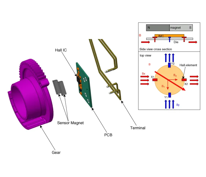
Throttle Position Sensor (TPS)
â–· Type : IC Rotation Sensor type
â–· Specification
Item
|
Sensor Resistance
|
Coil Resistance (Ω)
| 1.29 - 1.57 [20°C(68°F)]
|
Schematic diagrams
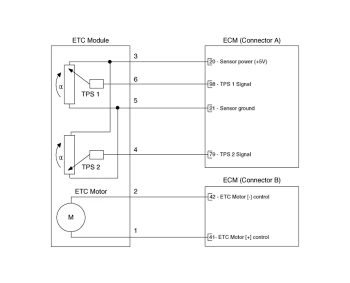
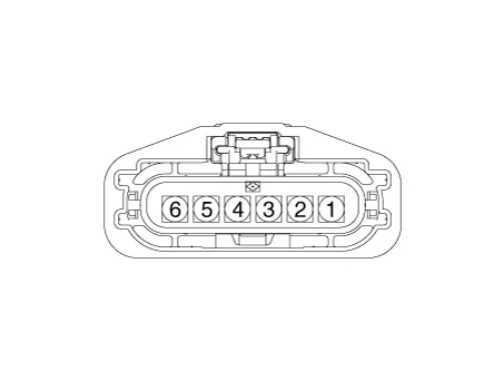
Harness Connector
Repair procedures
Throttle Position Sensor (TPS)
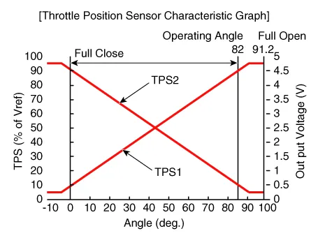
| 1. | Connect a diagnostic tool on the Data Link Connector (DLC). |
| 2. | Start engine and check output voltages of TPS 1 and 2 at C.T and W.O.T. Specification : Refer to Specification Section. |
|
ETC Motor
| 1. | Turn the ignition switch OFF. |
| 2. | Disconnect the ETC module connector. |
| 3. | Measure resistance between the ETC module terminals 1 and 2. |
| 4. | Check that the resistance is within the specification. Specification : Refer to Specification Section. |
|
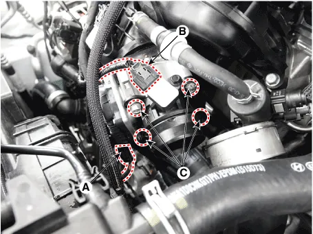
| 1. | Turn ignition switch OFF and disconnect the battery negative (-) terminal. |
| 2. | Remove the Intercooler outlet hose. (Refer to Engine Mechanical - "Intercooler") |
| 3. | Disconnect the ETC module connector (A). |
| 4. | Disconnect MAPS connector (B). |
| 5. | Remove the ETC mounting bolt (C). Tightening Torque : 9.8 - 11.8 N.m (1.0 - 1.2 kgf.m, 7.2 - 8.7 lb-ft) |
|
| 1. | Remove the ETC Module. (Refer to Engine Control System - "ETC System") |
| 2. | Keep the ETC module plate (A) open. 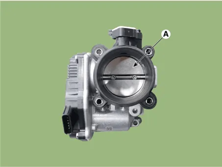
|
| 3. | Clean the pollutant in the throttle body with a soft cloth moistened with cleaning fluid. 
| •
| Do not spray cleaning fluid directly onto ETC. Use a lint free cloth moistened with cleaning fluid. |
| •
| Be careful not to clean the coating fluid around the shaft. If coating fluid is removed, idling control failure might occur by foreign substance inflow or excessive air leakage. |
|
|
| 4. | After cleaning, re-install the ETC module and then perform the ETC module learning procedure. (Refer to Engine Control System - "ETC System" - Adjustment) |
| •
| Install the component to the specified torques. |
| •
| Note that internal damage may occur when the component is dropped. In this case, use it after inspecting. |
|
| 1. | Install in the reverse order of removal. |
ETC Module Learning Procedure
Be sure to perform the ETC module learning procedure when replacing or re-installing the ETC module.
| 1. | Wait for 1 minute with the ignition switch ON. |
| 2. | Start the engine and hold the idle status for 15 minutes. |
| 3. | Waif for 1 minute with the ignition switch OFF. |
| 4. | Restart the engine, and check that the idle speed is stable. | •
| If the ETC module learning procedure is not performed after replacing or reinstalling the ETC module, MIL illumination with DTCs may occur. |
|
|
Description and operation
DescriptionBoost pressure sensor (BPS) is installed on top of intercooler output pipe to measures the pressure of supercharged air in the turbocharger.
Description and operation
DescriptionManifold Absolute Pressure Sensor (MAPS) is a speed-density type sensor and is installed on the surge tank. It senses absolute pressure of the surge tank and transfers the analog signal proportional to the pressure to the ECM.
Other information:
DescriptionThe immobilizer system will disable the vehicle unless the proper ignition key is used, in addition to the currently available anti-theft systems such as car alarms, the immobilizer system aims to drastically reduce the rate of auto theft.1.
Description and operation
Description 1.The photo sensor is located at the center of the defrost nozzles.2.The photo sensor contains a photovoltaic (sensitive to sunlight) diode. The solar radiation received by its light receiving portion, generates an electromotive force in proportion to the amount of radiation received which is transferred to

