Hyundai Elantra (CN7): ESC (Electronic Stability Control) System / ESC (Electronic Stability Control) Module
Components and components location
| Components |
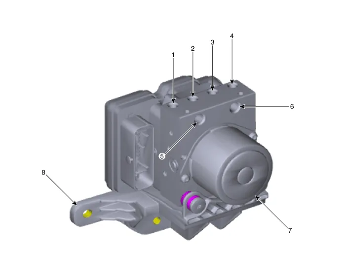
| 1. Front - right (FR) 2. Rear - left (RL) 3. Rear - right (RR) 4. Front - left (FL) | 5. MC2 6. MC1 7. ABS control module (HECU) 8. Bracket |
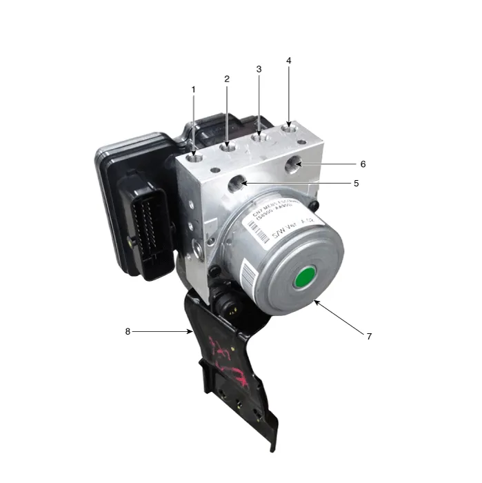
| 1. Front - right (FR) 2. Rear - left (RL) 3. Rear - right (RR) 4. Front - left (FL) | 5. MC2 6. MC1 7. ABS control module (HECU) 8. Bracket |
Repair procedures
| Removal |
| 1. | Turn ignition switch OFF and disconnect the negative (-) battery cable. |
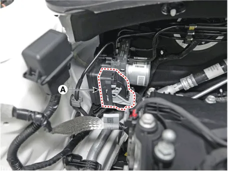
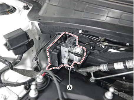
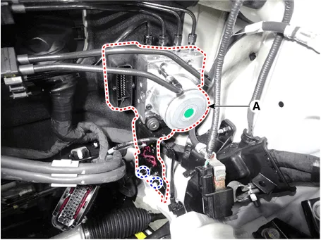
| 2. | Pull up the lock of the HECU connector and then disconnect the connector (A).
|
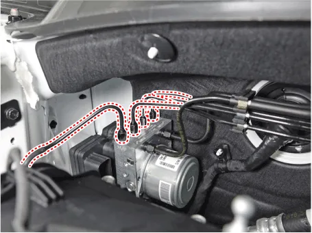
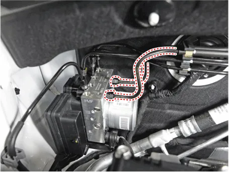
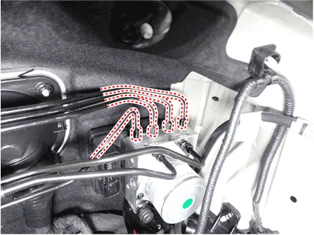
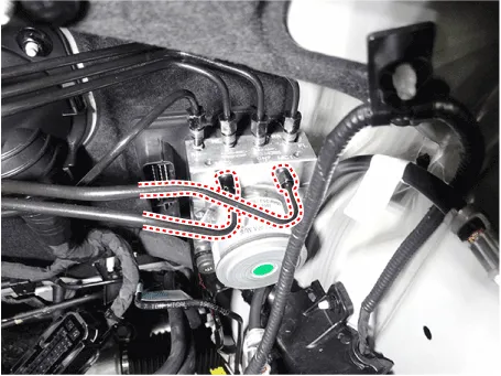
| 3. | Separate the brake tubes from the HECU by unlocking the nuts (6-ea) couterclockwise using a spanner.
|
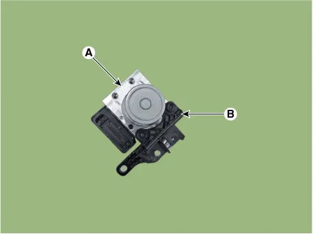
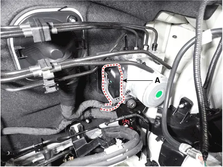
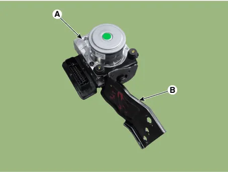
| 4. | Loosen the ABS control module mounting nut and then remove the ABS control module (A) from the vehicle.
|
| 5. | Separate the bracket (B) after remove the mounting bolt from the HECU (A).
|
| 1. | Turn ignition switch OFF and disconnect the negative (-) battery cable. |
| 2. | Remove the battery and battery tray. (Refer to Engine Electrical System - "Battery") |
| 3. | Pull up the lock of the HECU connector and then disconnect the connector (A).
|
| 4. | Separate the brake tubes from the HECU by unlocking the nuts (6-ea) couterclockwise using a spanner.
|
| 5. | Loosen the ABS control module mounting nut and then remove the ESC control module (A) from the vehicle.
|
| 6. | Separate the bracket (B) after remove the mounting bolt from the HECU (A).
|
| Installation |
| 1. | To install, reverse the removal procedure. |
| 2. | After installation, bleed the brake system. (Refer to Brake System - "Brake Bleeding Prcoedures") |
| Adjustment |
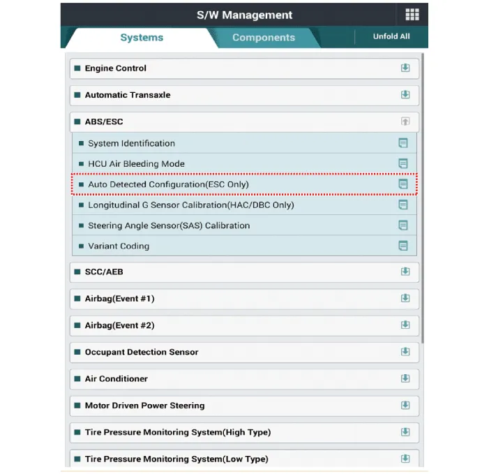
| 1. | Connect self-diagnosis connector (16pins) located under the driver side crash pad to self-diagnosis device, and then turn the self-diagnosis device after key is ON. |
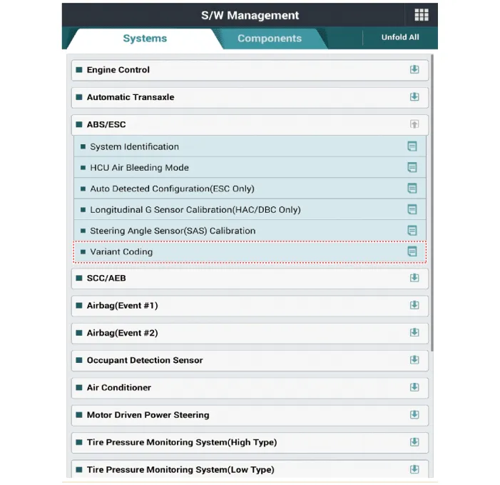
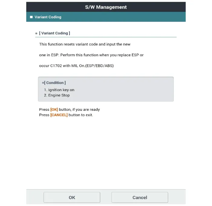
| 2. | Select the "vehicle model" and "ESP/ESC" on GDS vehicle selection screen, then select OK. [Variant Code Reset]
[Variant Coding]
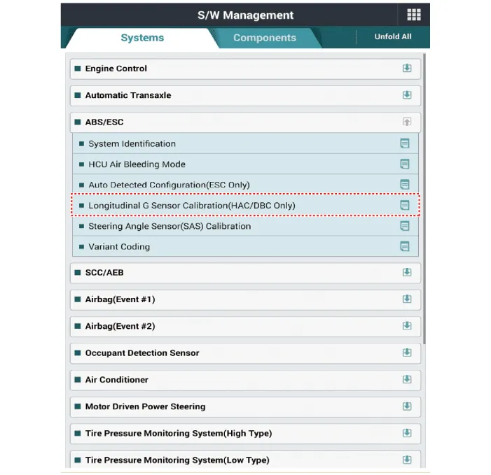
[Longitudinal G Sensor Calibration]
|
Terminal Function[EPB None Apply] PIN No Desciption Current max min 1Voltage supply for pump motor40A10 MΩ2Hazard switch1.
Description and operation Description1.The ESP OFF switch is for the user to turn off the ESP system.2.The ESP OFF lamp is on when ESP OFF switch is engaged.
Other information:
Hyundai Elantra (CN7) 2021-2026 Service Manual: Heater & A/C Control Unit (DATC)
Components and components location Components[This illustration shows the LHD type. RHD type is symmetrical.][Connector A] Pin No Function Pin No Function 1Battery9IGN22ILL+ (TAIL)10ISG Battery (+)3-11IGN14LIN BUS12HTD5-13-6-14-7-15-8RHEO (
Hyundai Elantra (CN7) 2021-2026 Service Manual: Components and components location
C
Categories
- Manuals Home
- Hyundai Elantra Owners Manual
- Hyundai Elantra Service Manual
- Rear Seats
- Engine Mechanical System
- Towing
- New on site
- Most important about car
