Hyundai Elantra (CN7): Interior Lights / Front lamps
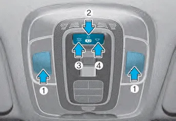
(1) Front Map Lamp
(2) Front Door Lamp
(3) Front Room Lamp ON
(4) Front Room Lamp OFF
Front map lamp:
Press either of these lens to turn the map lamp on or off. This light produces a spot beam for convenient use as a map lamp at night or as a personal lamp for the driver and the front passenger.
Front Door Lamp (
 ):
):
The front or rear room lamps come on when the front or rear doors are opened if the engine is running or not. When doors are unlocked by the remote key or smart key, the front and rear lamps come on for approximately 30 seconds as long as any door is not opened. The front and rear room lamps go out gradually after approximately 30 seconds if the door is closed. However, if the ignition switch is in the ON position or all doors are locked, the front and rear lamps will turn off. If a door is opened with the ignition switch in the ACC position or the OFF position, the front and rear lamps stay on for about 20 minutes.
Front room lamp
•
 :
:
Press the button to turn ON the room lamp for the front/rear seats.
•
 :
:
Press the button to turn OFF the room lamp for the front/rear seats.
WARNING Do not use the interior lights when driving in the dark. The interior lights may obscure your view and cause an accident. NOTICE Do not use the interior lights for extended periods when the vehicle is turned off or the battery will discharge.
Rear Room Lamp ( ): NOTICE Do not leave the lamp switches on for an extended period of time when the engine is turned off.
Other information:
Hyundai Elantra (CN7) 2021-2026 Service Manual: Front View Camera Unit
Schematic diagrams Circuit Diagram Repair procedures Removal1.Disconnect the negative (-) battery terminal.2.Remove the cover (A) & (B).3.Disconnect the front view camera unit connector (A).4.Separate the fixed points (A) of coupler.5.
Hyundai Elantra (CN7) 2021-2026 Service Manual: Warning Indicator
Components and components location Components1. BSD Indicator2. Side repeater lamp Repair procedures Inspection1.Disconnect the negative (-) battery terminal.2.Remove the front door trim.(Refer to Body - "Front door trim")3.Disconnect the power door mirror connector from the harness4.
Categories
- Manuals Home
- Hyundai Elantra Owners Manual
- Hyundai Elantra Service Manual
- Front Bumper
- Rear Seats
- Integrated Thermal Management Module (ITM)
- New on site
- Most important about car
