Hyundai Elantra (CN7): Manual Transaxle Control System / Control Cable
Components and components location
| Components |
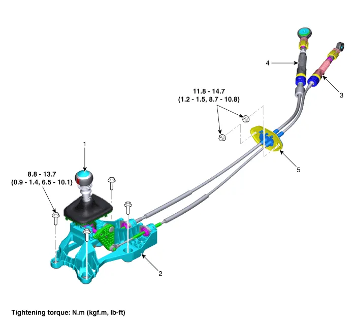
| 1. Shift lever knob & boots 2. Shift lever assembly 3. Select cable | 4. Shift cable 5. Retainer |
Repair procedures
| Removal |
| 1. | Remove the air cleaner assembly and air duct. (Refer to Engine Mechnical System - "Air Cleaner") |
| 2. | Remove the battery and battery tray. (Refer to Engine Electrical System - "Battery") |
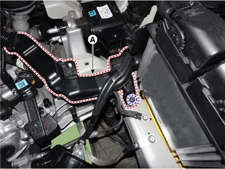
| 3. | Loosen the bolt and then separate the engine wiring (A).
|
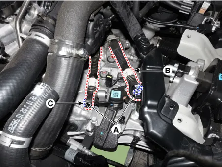
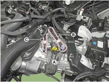
| 4. | Remove the snap pin (A) and then separate the shift cable (B) and the select cable (C) from the control shaft complete.
|
| 5. | Remove the floor console assembly. (Refer to Body - "Floor Console") |
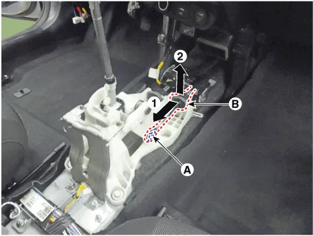
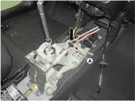
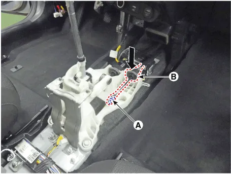
| 6. | Remove the snap pin (A) and then separate the select cable socket (B).
|
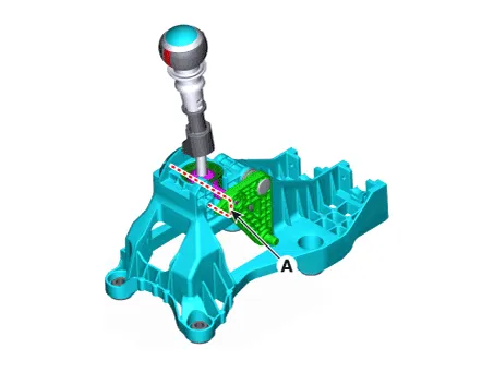
| 7. | Separate the cable socket (A) from the shift lever.
|
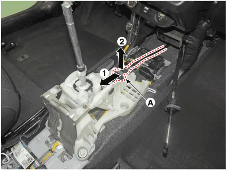
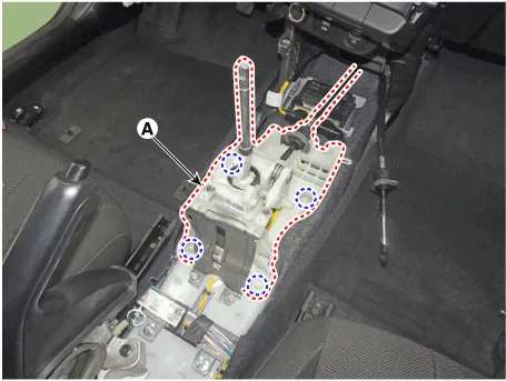
| 8. | Loosen the bolts and then separate the shift lever (A).
|
| 9. | Remove the shift cable end (A) and shift lever (B) by spreading the clips on both sides of the cable end.
|
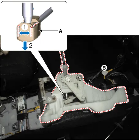
| 10. | Loosen the nuts and then removing the retainer (B).
|
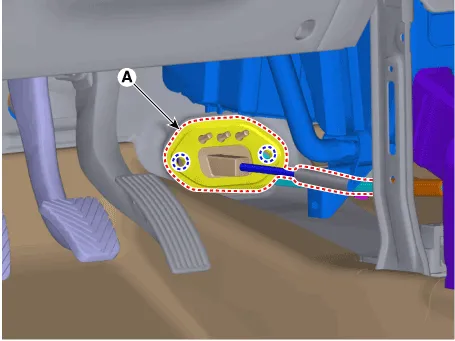
| 11. | Remove the control cable assembly (A) from the vehicle.
|

| Installation |
|

| 1. | Install the retainer (A) and then tighten the nuts.
|
| 2. | Install the shift cable end (A) on the shift lever (B).
|

| 3. | Install the shift lever (A).
|
| 4. | Install the shift cable socket (A).
|
| 5. | Install the select cable (B) and the snap pin (A).
|
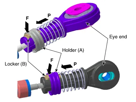
| 6. | Move the locker (B) in the direction of "F" with pulling the holder (A) in the direction of "P".
|

| 7. | Install the shift cable (B) and the select cable (C) and then insert the snap pin (A).
|
| 8. | Tighten the holder (A) to the "P" directions after fixing the rockers (B) in the "F" direction.
|
| 9. | Install the battery and battery tray. (Refer to Engine Electrical System - "Battery") |
| 10. | Install the air cleaner assembly and air duct. (Refer to Engine Mechnical System - "Air Cleaner") |
| 11. | Remove the 4th fixing pin (A).
|
| 12. | Install the floor console assembly. (Refer to Body - "Floor Console") |
|
Components and components location Components1. Shift lever knob & boots2. Shift lever assembly3. Select cable4. Shift cable5. Retainer Repair procedures Removal1.
Description and operation DescriptionComponent location Operation principle : Control shaft assembly is operated by shifting the shift lever.
Other information:
Hyundai Elantra (CN7) 2021-2026 Service Manual: Wireless Power Charging Unit
Components and positions Components Circuit diagram Circuit Diagram Repair procedures Removal • Handling wireless charging system parts by wet hands may cause electric shock. 1.Disconnect the negative (-) battery terminal.
Hyundai Elantra (CN7) 2021-2026 Service Manual: Components and components location
C
Categories
- Manuals Home
- Hyundai Elantra Owners Manual
- Hyundai Elantra Service Manual
- Front Radar Unit
- Engine Control / Fuel System
- Front Bumper
- New on site
- Most important about car

Copyright © 2026 www.helantra7.com - 0.0118