Hyundai Elantra (CN7): Front View Camera System / Front View Camera Unit
Schematic diagrams
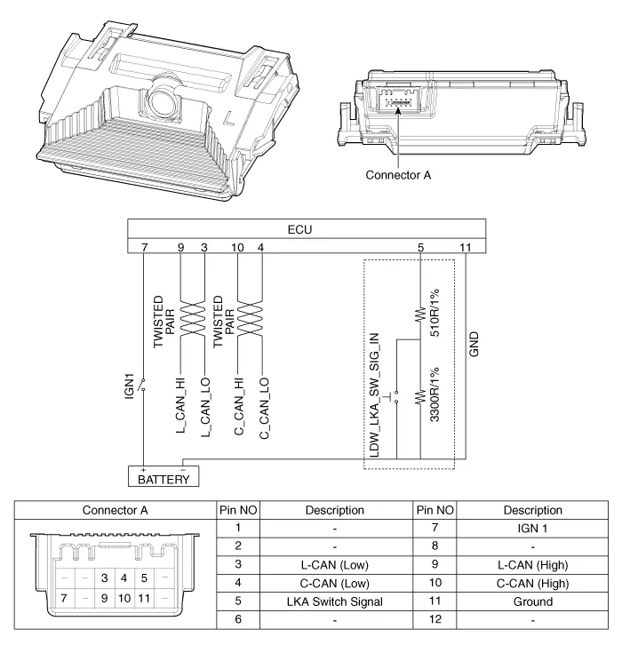
| Circuit Diagram |
Repair procedures
| Removal |
| 1. | Disconnect the negative (-) battery terminal. |
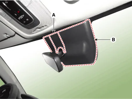
| 2. | Remove the cover (A) & (B).
|
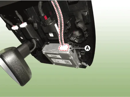
| 3. | Disconnect the front view camera unit connector (A).
|
| 4. | Separate the fixed points (A) of coupler.
|
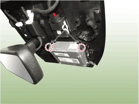
| 5. | Remove the front view camera (A).
|

| Installation |
|

| 1. | Install in the reverse order of removal. |
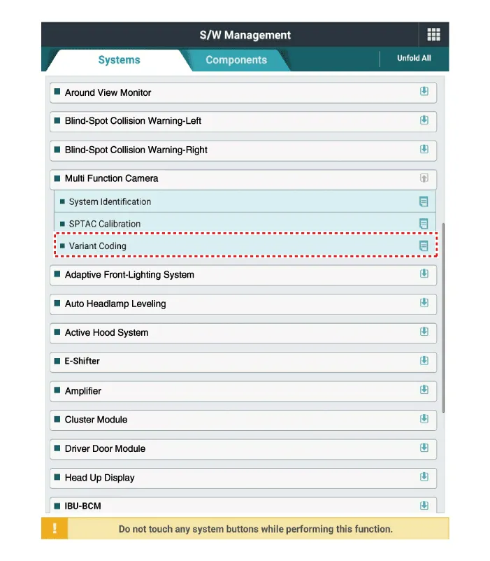
| 2. | When if replacing the front view camera with a new one, perform the "Variant Coding" procedure by using the Diagnostic Tools.
|
| 3. | Perform the front view camera unit calibration. (Refer to Repair procedures - "Service Point Target Auto Calibration (SPTAC)") |
Variant Coding When you need variant coding:– Replace Front View Camera with a new one※ EOL Variant Coding and calibration required for new replacementFront View Camera Variant CodingFront view camera variant coding makes it possible to operate functions for each vehicle type.
Other information:
Hyundai Elantra (CN7) 2021-2025 Service Manual: Ignition Switch Assembly. Repair procedures
Repair procedures Replacement1.Disconnect the negative (-) battery terminal.2.Remove the crash pad lower panel.(Refer to Body - "Crash Pad")3.Remove the steering column upper & Lower shroud.4.Remove the ignition switch and disconnecting the Key Warning / immobilizer connector.
Hyundai Elantra (CN7) 2021-2025 Service Manual: Evaporator Core
Repair procedures Replacement1.Disconnect the negative (-) battery terminal. 2.Remove the heater and blower assembly.(Refer to Heater - "Heater Unit") 3.Remove the heater core cover (A) after loosening the mounting screws.4.Pull out the evaporator core (A) from the heater unit.
Categories
- Manuals Home
- Hyundai Elantra Owners Manual
- Hyundai Elantra Service Manual
- Driver assistance system
- Drive Mode
- Engine Mechanical System
- New on site
- Most important about car
