Hyundai Elantra: ABS(Anti-Lock Brake System) / Front Wheel Speed Sensor
Hyundai Elantra (CN7) 2021-2025 Service Manual / Brake System / ABS(Anti-Lock Brake System) / Front Wheel Speed Sensor
Components and components location
| Components |
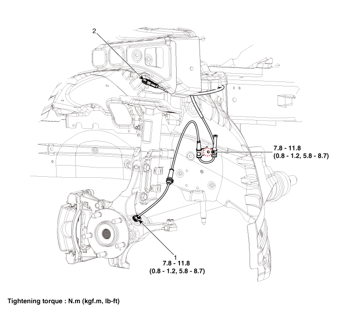
| 1. Front wheel speed sensor | 2. Front wheel speed sensor connector |
Repair procedures
| Removal |
| 1. | Turn ignition switch OFF and disconnect the negative (-) battery cable. |
| 2. | Loosen the wheel nuts slightly. Raise the vehicle, and make sure it is securely supported. |
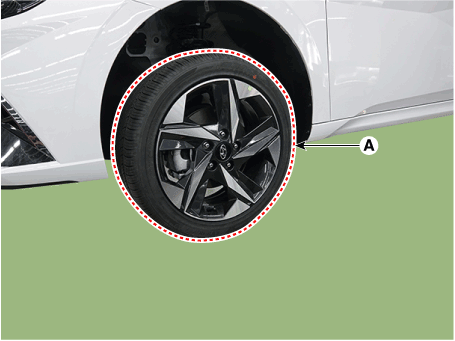
| 3. | Remove the rear wheel and tire (A) from the rear hub.
|
| 4. | Remove the front wheel guard. (Refer to Body - "Front Wheel Guard") |
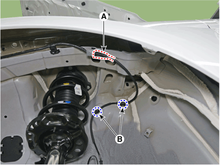
| 5. | Disconnect the front wheel speed sensor connector (A) and then remove the fixing clip (B).
|
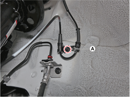
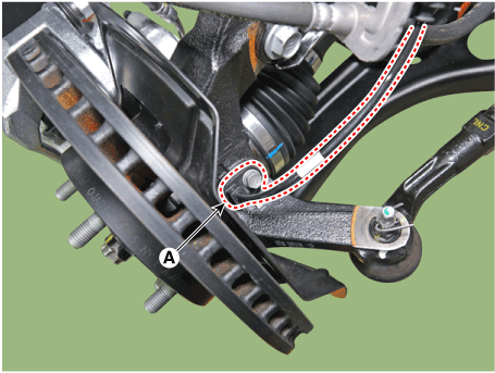
| 6. | Remove the front wheel speed sensor cable braket bolt (A).
|
| 7. | Remove the wheel speed sensor (A) from the Knuckle after loosening the mounting bolt.
|
| Installation |
| 1. | To install, reverse the removal procedure. |
| Inspection |
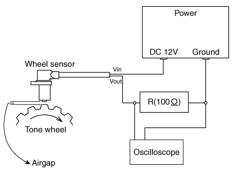
| 1. | Measure the output voltage between the terminal of the wheel speed sensor and the body ground.
|
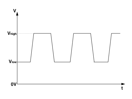
| 2. | Compare the change of the output voltage of the wheel speed sensor to the normal change of the output voltage as shown below.
|
 ESC (Electronic Stability Control) Module
Components and components location
Components[LHD]1. Front - right (FR)2. Rear - left (RL)3. Rear - right (RR)4. Front - left (FL)5. MC26. MC17. ABS control module (HECU)8...
 Rear Wheel Speed Sensor
Components and components location
Components[Rear torsion beam disc brake type]1. Rear wheel speed sensor2. Rear wheel speed sensor connector[Rear multi link disc brake type]1...
Other information:
Hyundai Elantra (CN7) 2021-2025 Service Manual: Accelerator Position Sensor (APS)
Description and operation DescriptionAccelerator Position Sensor (APS) is installed on the accelerator pedal module and detects the rotation angle of the accelerator pedal. The APS is one of the most important sensors in engine control system, so it consists of the two sensors which adapt individual sensor power and ground line...
Hyundai Elantra (CN7) 2021-2025 Service Manual: Climate Control Air Filter
Description and operation Description The climate control air filter is located in the blower unit. It eliminates foreign materials and odor. The particle filter performs a role as an odor filter as well as a conventional dust filter to ensure comfortable interior environment...
Copyright © 2025 www.helantra7.com


.png)