Hyundai Elantra (CN7): Controller / Heater & A/C Control Unit (Manual)
Components and components location
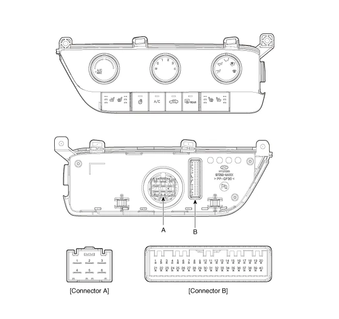
| Components |
| [This illustration shows the LHD type. RHD type is symmetrical.] |
|
Pin No
|
Function
|
Pin No
|
Function
|
| 1 | Low (Register specifications) | 4 | Middle Low (Register specifications) |
| 2 | Common (Register specifications) | 5 | Middle High (Register specifications) |
| 3 | Ground (Register specifications) | 6 | High (Register specifications) |
|
Pin No
|
Function
|
Pin No
|
Function
|
| 1 | Battery (+) | 21 | IGN2 |
| 2 | ISG B+ | 22 | IGN1 |
| 3 | ILL+ (TAIL) | 23 | Blower IS (PWM specifications) |
| 4 | Sensor REF (+5V) | 24 | - |
| 5 | Mode control actuator (Feedback) | 25 | - |
| 6 | Temperature control actuator (Feedback) | 26 | - |
| 7 | Intake actuator (Feedback) | 27 | Blower Max. On signal (Register specifications) |
| 8 | EVAP sensor (+) | 28 | - |
| 9 | AMB sensor (+) | 29 | PTC relay |
| 10 | Mode control actuator (Vent) | 30 | - |
| 11 | Mode control actuator (DEF) | 31 | - |
| 12 | Temperature control actuator (Cool) | 32 | - |
| 13 | Temperature control actuator (Warm) | 33 | P_CAN High |
| 14 | Intake actuator (FRE) | 34 | P_CAN Low |
| 15 | Intake actuator (REC) | 35 | Blower INH (PWM specifications) |
| 16 | HDT | 36 | Blower PWM (In) (PWM specifications) |
| 17 | - | 37 | ECV (+) |
| 18 | - | 38 | ECV (-) |
| 19 | Blower signal (On) (Register specifications) | 39 | Sensor ground |
| 20 | ILL- (RHEO) | 40 | Ground |
Repair procedures
| Replacement |
| 1. | Disconnect the negative (-) battery terminal. |
| 2. | Remove the crash pad lower panel. (Refer to Body (Interior and Exterior) - "Crash Pad Lower Panel") |
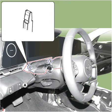
| 3. | Remove the steering column shroud upper panel (A).
|
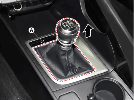
| 4. | Remove the gear knob & boots (A) pull both of it up.
|
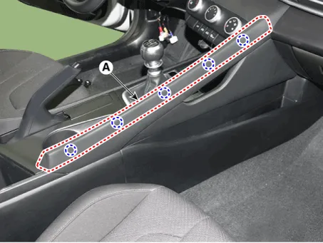
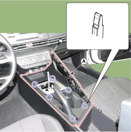
| 5. | Using a screwdriver or remover, remove the floor console side garnish (A).
|
| 6. | Remove the parking brake cover (A).
|
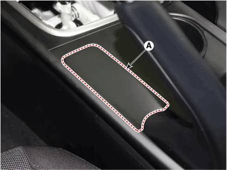
| 7. | Using a screwdriver or remover, remove the console upper cover (A).
|
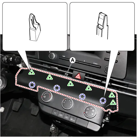
| 8. | Using a screwdriver or remover, remove the crash pad garnish [CTR] (A).
|
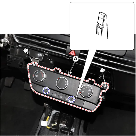
| 9. | After loosening the mounting screws, remove the A/C & heater controller unit (A).
|
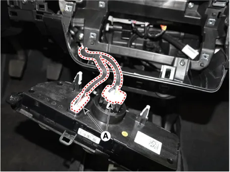
| 10. | Disconnect the A/C & heater controller connectors (A).
|
| 11. | To install, reverse the removal procedure.
|

Components and components location Components[This illustration shows the LHD type. RHD type is symmetrical.][Connector A] Pin No Function Pin No Function 1Battery9IGN22ILL+ (TAIL)10ISG Battery (+)3-11IGN14LIN BUS12HTD5-13-6-14-7-15-8RHEO (ILL-)16Ground Repair procedures Self Diagnosis1.
Other information:
Hyundai Elantra (CN7) 2021-2025 Service Manual: Specifications
SpecificationAir Conditioner Item Specification CompressorTypeGamma 1.6 MPI, Gasoline 2.0 NU MPI, Gasoline 1.6 T-GDI : 6HVx14Gasoline 1.6 MPI : 6HVe14Oil type & CapacityFD46XG (IDEMITSU) 100 ± 10 g Pulley type6PK-TYPEDisplacement145 cc/revExpansion valveTypeBlock type RefrigerantTypeR - 134
Hyundai Elantra (CN7) 2021-2025 Service Manual: Troubleshooting
Diagnosis with Diagnostic tool1.In the body electrical system, failure can be quickly diagnosed by using the vehicle diagnostic system (Diagnostic tool).The diagnostic system (Diagnostic tool) provides the following information.(1)Fault Code Searching : Checking failure and code number (DTC)(2)Data Analysis : Checking the system input/output data s
Categories
- Manuals Home
- Hyundai Elantra Owners Manual
- Hyundai Elantra Service Manual
- Rear Seats
- Vehicle Information
- Suspension System
- New on site
- Most important about car
